• Steel Soldiers now has a few new forums, read more about it at: New Munitions Forums!

  • Microsoft MSN, Live, Hotmail, Outlook email users may not be receiving emails. We are working to resolve this issue. Please add support@steelsoldiers.com to your trusted contacts.

MEP-004A, No output

Guyfang

Moderator
Staff member
Moderator
16,766
24,078
113
Location
Burgkunstadt, Germany
Update,
uninstalling the float was a back breaker and half of the screws you cant see.
You have to use a stubby flat head screw driver because of the confined area vertically.
Would have been better if the screws were hex head.
Went thru Guys instruction's for the test. No Bueno. Fuel gage said full no matter what the position the float was in.
Then Peter said it was totally mechanical and a easy fix.
Since it is mechanical I commenced to disassemble it. Peter was correct that it can be fixed.
I found corrosion on the surfaces and the surfaces were crusty. One surface cleaned up with scotch bright and the other had to be sanded.
After that Peter gave me instructions to test with an OHM meter. I did this before and after the fix. Before the readings were not good at all, no continuity on some positions. He blessed it with a meter reading of 46.9 ohms in the full position and 8.7 ohms in the empty position after fix.
So next I will reinstall the float and test to Guys test procedure. The test procedure is definitely a two person job.
I sent Peter some pics of the float disassembled and he said he would post it here and enhance them.
Kris

Well, I could have told you its a PITA. But didn't want to give you a reason to put it off until the second coming.
You are becoming a first class generator mech!
So put some hex head screws back in it!
Peter gave you instructions that came straight out of the TM. Never hurts to look in them before doing anything you have never done before.
You are lookin good!
 

peapvp

Well-known member
Steel Soldiers Supporter
1,115
1,229
113
Location
Basehor, KS
Ok,

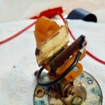
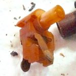
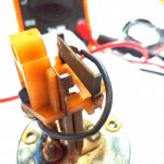
The main issue with those floats is the problem of corrosion. These units have 2 wipers, with one making contact with the single ended resistor winding (right side) which connected to the Connector Pin and the metal plate on the left side which makes contact with the chassis ground.

f9o4QEqM.jpgqp-b4JLr.jpegSy2F4xvF.jpg


The manual has the following specification:

Full Tank: 0.1 to 1 Ohm

Empty Tank: 27 Ohm +/- 2 Ohm

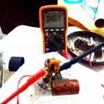
After Chris fixed his potentiometer by cleaning up the contacts, it showed 47 Ohm, which does not surprise me as to the info in the manuals.

Dexoit may would have worked better then sanding paper / scotch bright - but we worked with what we had at hand.

After cleaning, especially with the sanding method, it maybe useful to add contact grease to prevent or slow down future corrosion / oxidation

glF9Capw.jpg


P.S. I increased exposure and brightness on the pictures Kris had texted me, so the details would be more visible
 

Guyfang

Moderator
Staff member
Moderator
16,766
24,078
113
Location
Burgkunstadt, Germany
1. Seen worse.
2. Good job of cleaning it up.
3. This is a "New" type to me. never seen one just like this. The function is the same as what I know, but materials are different.
4. Simple repair. PITA to get out and back in, but the repair itself was not bad. Most folks would toss it and try and get a new one.

ALMOST everything is repairable, if you try. I always try. Worse thing that can happen is it don't work when you get done. If just half the folks would give just half the effort to do what you have done, they would save a TON of money, and have a much better understanding of their gen set.

So, we have any other short comings? Your kicking butt now, and on a roll.
 

Guyfang

Moderator
Staff member
Moderator
16,766
24,078
113
Location
Burgkunstadt, Germany
Ok,

The main issue with those floats is the problem of corrosion. These units have 2 wipers, with one making contact with the single ended resistor winding (right side) which connected to the Connector Pin and the metal plate on the left side which makes contact with the chassis ground.

View attachment 782570View attachment 782571View attachment 782572


The manual has the following specification:

Full Tank: 0.1 to 1 Ohm

Empty Tank: 27 Ohm +/- 2 Ohm

After Chris fixed his potentiometer by cleaning up the contacts, it showed 47 Ohm, which does not surprise me as to the info in the manuals.
This is why you should ALWAYS try the thing out after Test/repair. Too many folks look at the spec's and say, "Its out of tolerance". And toss it. ALWAYS try it out. The books are famous for being wrong. Or out of spec's? A classic example of the difference between theory and practice.
Dexoit may would have worked better then sanding paper / scotch bright - but we worked with what we had at hand.

After cleaning, especially with the sanding method, it maybe useful to add contact grease to prevent or slow down future corrosion / oxidation

View attachment 782573


P.S. I increased exposure and brightness on the pictures Kris had texted me, so the details would be more visible
.
 

peapvp

Well-known member
Steel Soldiers Supporter
1,115
1,229
113
Location
Basehor, KS
Guy, I am wondering now if the old version of this float you know had a 27 Ohm potentiometer and this newer version here has 47 Ohm? Or was the resistance with 27 Ohm another typo in the manual?

i guess we will find out once Kris checks it by hooking it up to genset and manually moving the float.......


Guyfang

Moderator
Staff member
Moderator
16,766
24,078
113
Location
Burgkunstadt, Germany
No, can not remember, nor when I looked into the great NSN pool of info, was it present. It would be interesting to pull a sending unit out of a MEP-802 or 803, and see what it has for an ohms reading. I looked for the tech spec's and that was not listed. I think the mounting base is the same, as all other gen sets have. 5 screws, and the gasket, if I remember right looks the same. Might be worth the time for someone to take a look see.
 

KLChurch

New member
475
2
0
Location
Montgomery/TX
So we will see if the float is the correct unit for the gen. While disassembling the float it had a rubber gasket plus some silicone gel. Maybe this float was not the original.
The reason I have not test to Guys test procedure is that I had to actually work for a living. Plus it is colder than a witches tity. Brain is going to call me a pussy but that's OK.
Kris
 

KLChurch

New member
475
2
0
Location
Montgomery/TX
The H1 in my pic will be finished with a four cyl Cummins before Xmas. Cant wait to drive it and paint it to so to thank you for your service.
On the tailgate it will have H1.2 The way the Humvee should have been designed. No electronics. Total mechanical.
.1 is the engine with a mechanical IP and the .2 is the trany with no longer electronic necessity.
Kris
 
Last edited:

Guyfang

Moderator
Staff member
Moderator
16,766
24,078
113
Location
Burgkunstadt, Germany
So we will see if the float is the correct unit for the gen. While disassembling the float it had a rubber gasket plus some silicone gel. Maybe this float was not the original.
The reason I have not test to Guys test procedure is that I had to actually work for a living. Plus it is colder than a witches tity. Brain is going to call me a pussy but that's OK.
Kris
Most of these sending units look just like that. Some have paper gaskets, some rubber. For some reason folks just have to smear RTV on everything. Mostly they use something that turns to silly putty, after exposure to diesel.
 

KLChurch

New member
475
2
0
Location
Montgomery/TX
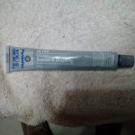
sealant.jpgThis is the sealant I picked to seal the float.
It says it is a rubberized sealant.
The rubber gasket is not in good condition and I'm not electing to reinstall.
Kris
 

KLChurch

New member
475
2
0
Location
Montgomery/TX
update
I assembled the float into the tank without checking to Guys test procedure.
I took a gamble that it was OK.
That was yesterday. Wanted the sealant to cure.
Today I started the gen and the fuel gage seems to be accurate. Before I put the float in I looked into the hole of the tank and determined the fuel was 1/2 to 3/4 full. Not 1/4 to 1/2 empty. LOL
The gage said it was slightly over 3/4 full.
So I let the gen run for 30 mins under load to see if the gage went closer to empty. It did so and now it is exactly 3/4 full. (Now the hour meter says 8 hours more than when I got it) No refill of fuel
All other gages seems to be performing correctly.
So next I will try a full load test.
Kris
 

KLChurch

New member
475
2
0
Location
Montgomery/TX
Brian
I sent you a private mess

Still I haven't done the heavy load test.

Have very important tasks to do on my land and work.

Sending Brian my original switch to examine. This will be very important for his study and opinion, because from what I see on the internet this seems to be a common problem when they flip the switch many times while trying to start the gens.
The switch Brian sent me no longer has this problem. Fires off with the first flip.
Thank God for Brian
Kris
 

DACollins

Member
48
12
8
Location
Sandy Springs, SC
Kris,

There is also a tool called a solder remover. It is an attachment that goes on, or replaces your soldering iron tip. What it does is heat up the solder, (just like your normal soldering iron) and when the solder flows, you press a big rubber bulb, (Kinda like a kids toy tricycle horn) and blow away solder. Or, you press the bulb slowly, and when the solder flows, let the bulb go, and the vacuum sucks off the solder from your solder point. If It wasn't 23:24 I would go out to the garage and get one to show you a picture. Takes a little practice too use, but once you master it, its pretty darned handy.
I've had great luck with a roll of solder wyck. Just braided flat copper that absorbs the solder when heated. Very neat and clean.
 
Top