• Steel Soldiers now has a few new forums, read more about it at: New Munitions Forums!

  • Microsoft MSN, Live, Hotmail, Outlook email users may not be receiving emails. We are working to resolve this issue. Please add support@steelsoldiers.com to your trusted contacts.


Power Distribution Panel M1083A1 10/98

Lugnuts

Active member
Steel Soldiers Supporter
257
201
43
Location
Myakka City, FL
There is a flasher module behind the passenger kick panel. There should be a breaker for each circuit on the board though. That is the only breaker panel on the truck. There are 2 large relays on the underside but if your truck starts then they are working. Do you have a panel cover there is a diagram showing what relay/breaker does what.
I am assuming that the 1083 has a relay for the horn because the size of the wire I don't think would support 12vdc or 24vdc very far on distance. There is no relay on the board for horn. I was using the 1078 schematic for reference and mode of thinking and since that is not pertinent to the 1083 I really am just running on assumptions.
The two large relays you mention earlier you said were on the underside, underside of what?
 

Lugnuts

Active member
Steel Soldiers Supporter
257
201
43
Location
Myakka City, FL
don't think turn signal flasher is on the board. Well it was not in A0 if I recall right reading that. Thus probably not on A1 either. Thus, well could be horn is not either.
If they are not on the board, where are they? I have dismantled quite a bit and frustrations are looming. I know in the center of the dash were electrical connections as per 1078 but did they slip any components in there? Thank you for your time
 

Awesomeness

Well-known member
Steel Soldiers Supporter
1,811
1,508
113
Location
Orlando, FL
If they are not on the board, where are they? I have dismantled quite a bit and frustrations are looming. I know in the center of the dash were electrical connections as per 1078 but did they slip any components in there? Thank you for your time
It would have to be somewhat obvious. It could only be in the cab on an open, unprotected board. If it was outside somewhere it would have to be in a sealed box, which would be easy to find.
 

coachgeo

Well-known member
4,929
3,314
113
Location
North of Cincy OH
If they are not on the board, where are they? I have dismantled quite a bit and frustrations are looming. I know in the center of the dash were electrical connections as per 1078 but did they slip any components in there? Thank you for your time
sounds like it is time to search the A1Tm's. Truly respect how much a PITA it is to search them but looks like your at that point. Even an A0 TM might shed some light. (Early A1 TM I believe is sold in the classifieds (cause it takes time to extract from proprietary non public software). If not there is link in the [Announcements ] / "Hall of Knowledge" thread on the LMTV MTV Facebook group to the information on where to get the. A0 is free, found here in first section of this board.

also a search in this forum ... for a pdf for just A1 electric schematics. for some reason thinking someone posted that seperate.
 

Lugnuts

Active member
Steel Soldiers Supporter
257
201
43
Location
Myakka City, FL
View attachment 795357
Hope this helps. If you are having issues with the turn signals and the horn, I would look at the Turn signal switch. I have seen many of them go bad.
sounds like it is time to search the A1Tm's. Truly respect how much a PITA it is to search them but looks like your at that point. Even an A0 TM might shed some light. (Early A1 TM I believe is sold in the classifieds (cause it takes time to extract from proprietary non public software). If not there is link in the [Announcements ] / "Hall of Knowledge" thread on the LMTV MTV Facebook group to the information on where to get the. A0 is free, found here in first section of this board.

also a search in this forum ... for a pdf for just A1 electric schematics. for some reason thinking someone posted that seperate.
When I find it I'll definitely post it. Thanks for the help/ Lugnuts
 

Lugnuts

Active member
Steel Soldiers Supporter
257
201
43
Location
Myakka City, FL
View attachment 795357
Hope this helps. If you are having issues with the turn signals and the horn, I would look at the Turn signal switch. I have seen many of them go bad.
I did check for continuity and breaking continuity and the switch appears fine. I can even see that I have power in on the switch on the flasher side because I get a blinking on that leg. No sound from a flasher so could be electronic. Stimulated the wires designated to the flashers, marker lights, horn, and nothing. Not even smoke. Oh well the search continues./ Thanks for the input
 

Lugnuts

Active member
Steel Soldiers Supporter
257
201
43
Location
Myakka City, FL
An update on what I have accomplished
After checking Turn Signal Switches and finding power to work them/ After finding the horn and testing that/ I had to go on to some other business for a couple of weeks and upon my return I found my truck would not start nor fire up any lights/ Proceeded to test batteries and found all the power I needed/ Now to consider what gnomes are laughing I found in the bottom of my wiring under the speedometer two sockets, J912 and J913, perfect match/ I had not unplugged these to begin with but now in plugging these together all the lights went on the dash and the low air whine was ripping even without the power switch into the on position/ So then I went to start the truck and with a 10 second run it proceeded to shut down like it had lost its fuel prime/ At this time I begin to smell the undesired smell of electrical cooking on simmer/ I unplug J912/J913 and smell lessens/ My little dash module with the turn signal indicators has a faint wisp of smoke/ So after checking the arrangement of wires and finding no hots to ground I plug J912/913 together and try again/ Smell returns but I might as well play/ I begin to move the wiring connections on the board and my turn signal/ hazard lights/ horn begin to work/ Truck still starts momentarily and now I notice that the LED for Start Inhibit is illuminated/ That is where I am, writing to ask a couple of questions--- is that dash piece with the indicators a separate module of some computer origin? It does have a printed circuit board/ Secondly--- what triggers a Start Inhibit shut down? Is it computer activated and by what Inputs/ Maybe a little board with turn signal indicators???
PS> I am still looking for a Workshop Manual for this unit. I am also asking if any one has a description and map for the J912 and 913 socket? All help greatly appreciated
 

coachgeo

Well-known member
4,929
3,314
113
Location
North of Cincy OH
An update on what I have accomplished
....Now to consider what gnomes are laughing I found in the bottom of my wiring under the speedometer two sockets, J912 and J913, perfect match/ I had not unplugged these to begin with but now in plugging these together.... a faint wisp of smoke....
well poops :poop:
lol..... think you have discovered why that truck was auctioned... "oops...... smoke and burning wire.... let's move this one up to Top of the list of".. "send it off for auction":p
 

coachgeo

Well-known member
4,929
3,314
113
Location
North of Cincy OH
well poops :poop:
lol..... think you have discovered why that truck was auctioned... "oops...... smoke and burning wire.... let's move this one up to Top of the list of".. "send it off for auction":p
Believe there is a few who have bits and pisses of A1 manuals that may cover those plugs... if I did would not quite know what to search inside the doc/images to even send you the right ones. Hopefully someone who is pretty smart and has the right bits will post up soon.
 

Lugnuts

Active member
Steel Soldiers Supporter
257
201
43
Location
Myakka City, FL
Believe there is a few who have bits and pisses of A1 manuals that may cover those plugs... if I did would not quite know what to search inside the doc/images to even send you the right ones. Hopefully someone who is pretty smart and has the right bits will post up soon.
LOL! Love the encouragement dingleberry. LOL Nobody has fessed up to having a schematic or a workshop manual. The auction will probably be over by the time I find one but I will pursue. Have a great Memorial Day and thanks to all who have served.
 

Lugnuts

Active member
Steel Soldiers Supporter
257
201
43
Location
Myakka City, FL
It has been a while since I last wrote on the electrical issues. If I ever get bored with life I go and work on the 1083A1. I can repair a problem and then close the door on the cab, come back a day later, and I'll have a new problem.
I got the turn signals working, the horn is now working and what I did to accomplish this I really don't have a clue. I pulled plugs, checked connections, and replugged, close the door and went away for the day and lo and behold when I came back they were working.
Now I have a starting issue. Actually it is a transmission issue of which the military workshop manual doesn't seem to list.
I started the truck to build air to move it and maybe go for a ride. Truck started fine, built air, released brakes and went to select gear on the keypad. When I did the transmission wouldn't go into gear. So I hit the double arrows and all the lights went out. OK! So I said self shut it off and lets reset the computers and go again.
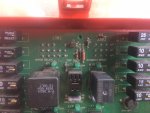
Well that where it sits. When I powered up again all dash lights and alarms responded normally, The Allison had nothing in the window but the mode light was on. The truck will not start by the button but can jump the solenoid and it will start that way. I noticed that on the Power Distribution Panel that there is a Neutral Light and I am wondering if that is suppose to light to indicate neutral? and give clearance for the system to start and function.
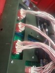
I did go back and check the Diode Box Connections in the event they were bad and that wasn't the problem. My next step is to see if the Transmission Control Module has power.

I guess I am writing this to ask if any has had this problem and where they found the fix?
Is that neutral light on the PDP suppose to be lit in order to start?
What does the mode light lit on with nothing else powered indicated?
It has been suggested before to Auction this unit off but now it's the conquest that is a challenge.
If you are bored with life get a 1083A1

Thank you for taking the time
Lugnuts
 

InspectorGadget

New member
4
3
3
Location
Lexington, KY
I would look at the under side of the PDP to make sure you do not see any corrosion, bad solders or burn marks. Also check the wiring under the PDP to ensure critters have not been in there chewing on wires.
Attached are some Schematics I had, pay attention to the serial numbers. FMTVA1 Schematic is S/N18549 & Below and S/N 18550-99,999. FMTVA1R Schematic is S/N 100,000-104,720 and 104,721 UP.
 

Attachments

Lugnuts

Active member
Steel Soldiers Supporter
257
201
43
Location
Myakka City, FL
Dude, you are like my HERO!!! I haven't mastered how to give you brownie points for this on the site but be it known I have been looking for these schematics for a while. Went to National Guard, they gave me everything they had but as far as they went was to the "10" Operators Manual.
If you are familiar with these trucks, is the neutral LED suppose to be lit in order to start it??
Thank you, Lugnuts
 
Last edited:

Lugnuts

Active member
Steel Soldiers Supporter
257
201
43
Location
Myakka City, FL
I am going back to a discussion earlier in this thread that discussed the Power Distribution Panel on the 1083A1. I am wondering if anyone has one for sale? I think NDT showed me a picture of one to clarify what I had.
I am definitely becoming more intimate with this truck and I think becoming to understand the thinking behind the board. It real in theory is and was a great design. The way it has test ports for connections and whole segments of the board deal with just the one plug which by the way is labeled on the board. But when I was looking for "Neutral" signal coming in at one spot and isolating that one spot by removing wires and relays I could see it in that block on the board in about 6 different places which it wasn't suppose to be. Don't no how that could be but it was.
I have a feeling that I am discovering the reason for the gnomes.
Lugnuts
 
Last edited:

Lugnuts

Active member
Steel Soldiers Supporter
257
201
43
Location
Myakka City, FL
I would look at the under side of the PDP to make sure you do not see any corrosion, bad solders or burn marks. Also check the wiring under the PDP to ensure critters have not been in there chewing on wires.
Attached are some Schematics I had, pay attention to the serial numbers. FMTVA1 Schematic is S/N18549 & Below and S/N 18550-99,999. FMTVA1R Schematic is S/N 100,000-104,720 and 104,721 UP.
[/QUOTE
Sir
Would you happen to have the Socket Illustrations for the PDF on the unit which we are speaking of. I am especially looking for Socket J302 but having all of them would be really nice. That would be J301 through J309. Matter of fact, any other information you have would be priceless to me.
Thank you
Lugnuts
 

Lugnuts

Active member
Steel Soldiers Supporter
257
201
43
Location
Myakka City, FL
On the board are numbers denoting what socket number is on the rear and with this there a diagrams telling what wires go into it and there location. Looking specifically for J302 but if someone had J301- J309 and wouldn't mind sharing them I would be pleased and could continue know exactly what I am doing.
Thank you
Lugnuts
 

Attachments

Top
AdBlock Detected

We get it, advertisements are annoying!

Sure, ad-blocking software does a great job at blocking ads, but it also blocks useful features of our website like our supporting vendors. Their ads help keep Steel Soldiers going. Please consider disabling your ad blockers for the site. Thanks!

I've Disabled AdBlock
No Thanks