springer1981
Well-known member
- 861
- 1,184
- 93
- Location
- Maine
Steel Soldiers now has a few new forums, read more about it at: New Munitions Forums!

.Still waiting on rivets for the tailgate hinges but managed to paint the tailgate.
View attachment 863481
View attachment 863482
View attachment 863483
Thanks!.
Looks Sharp!
.

Great work. Why not use a Dremel to round off the rivets? Mark the center area and then just use a drimel to gently take off excess material surrounding the contact area. Simple and fast and easy for someone with your skill set.In a previous post about the ignition switch I mentioned I might try to upgrade it for increased current capability (more AMPS). During my locking steering column modification I cut open the old Chinese key switch ignition and found the contact plate was burnt and melted. This was partially a result of the brass material used not to mention the thickness.
In the new ignition switch the contact plate is made out of solid copper and not brass. This is a bonus however the contacts in the plastic cap are merely bent over copper and the wires get soldered to the tab sticking out. In higher current situation relying on just solder to hold is not good. Screw or crimp terminals would be much better because it is physically held in place unlike solder that is more like gluing it in place. Also the switch insulation appears to be plastic but may have some thermal qualities to it.
My goal would be to build a replacement for the contacts, insulation and contact plate. Using a thermal fiber insulation, thicker contact plate, increased contact area and screw terminals it would significantly improve current handling capability of the entire switch. So I ordered some .042 copper plate, copper rivets, copper screw contacts and thermal fiber insulation.
View attachment 864240
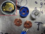
I don't have the insulation yet but today I started with the contact plate. In the upper left corner you can see the brass contact plate with the burnt and melted contact. On the bottom there are 2 copper contact plates, the one on the left is .030 copper with dimple contacts pressed into the copper. It's the original contact plate for the blue switch you see in the middle. The copper contact plate on the bottom right is the one I built. I cut it out of .042 copper plate then located and drilled for the rivets. Because the rivets have a lot more contact area I had to adjust the location and trim one edge so the paths don't overlap when turning the switch. The dimple contact has a very small point of contact vs the large flat rivet. I'm still waiting for the thermal fiber but I will post updates when I make the new cap. I've never made a switch before but if some kid in China can do it, so can I.
View attachment 864242
I'm not sure what you mean. I don't want to round off the rivets. I want maximum contact area and making them smaller reduces the contact area. IGreat work. Why not use a Dremel to round off the rivets? Mark the center area and then just use a dremel to gently take off excess material surrounding the contact area. Simple and fast and easy for someone with your skill set.
That’s not really the way electrical contacts on this type of device typically work. If you have a long-flat contact next to another long-flat contact, they can unintentionally weld themselves to each other. To prevent that and to help more carefully direct the electricity path, there is usually a pointed surface that sticks up beyond the flat surface. Gently rounding off the rivets would be the way to go. Usually, two different substances are utilized, one hard and one soft, in order to prevent wear and to prevent electrical arcing causing welding and adhesion. By focusing the electricity, it also helps the electrical connection bypass any small amounts of corrosion from oxidation With the pointed surface also mechanically damaging that oxidation to allow for electrical contact.I'm not sure what you mean. I don't want to round off the rivets. I want maximum contact area and making them smaller reduces the contact area. I
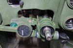


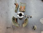
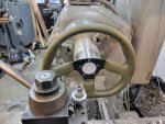
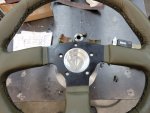
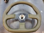
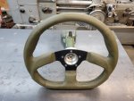
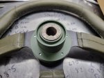
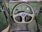
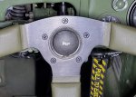
The steel hub was left with a rough surface and pressed into the aluminum adapter. About .001-.0015 press fit. I was going to put two 1/4x20 socket head screws in each side but after pressing in the hub, it was not needed.So how did you mount the original hub to the aluminum piece that you made? Looks amazing. Is it the same distance from you as the stock wheel? I don’t want mine any closer.

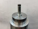

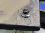
I came across that in the TM's. Looks like they might have changed them or retrofitted them. I think they also have spacers inside the tailgate for the top 3 holes on each side for the bolts.I had some tailgates that had hinges bolted to the body. This may be why.
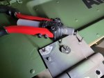
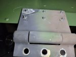
.Today was a little slow so I built this handy battery carrier. I'm going to test it this weekend.
View attachment 865494

