• Steel Soldiers now has a few new forums, read more about it at: New Munitions Forums!

  • Microsoft MSN, Live, Hotmail, Outlook email users may not be receiving emails. We are working to resolve this issue. Please add support@steelsoldiers.com to your trusted contacts.


My new 1992 M998 Avenger

springer1981

Well-known member
844
1,147
93
Location
Maine
.
Interesting... My battery carrier is a really large fan belt (twice as wide as a belt on my Cummins for example) Rubber between the battery posts gives me more flexible with different battery sizes.

GUESSING you must have some sort of insulator between the posts and the metal carrying handle?
Just to be safe and hope no one makes one, it's a joke LOL
 

springer1981

Well-known member
844
1,147
93
Location
Maine
I was interested in changing out my old turn signal switch for a self canceling switch but in my case due to the shortened steering column. Since I bought a self canceling switch I mounted it to my stock length steering column to see if it would work with the Key ignition/steering column lock. Because of the steering column lock modification it moves the turn signal switch out about 1/2". I had to make and replace a part on the turn signal switch and now it works. The self canceling switch I bought came with the canceling ring for the steering wheel. In the epay auction it said "Ring does not look original", what it should have said is "I 3D printed this ring and it looks like crap". It was deception by omission.

After figuring out how the self canceling works I think I can modify my old style turn signal switch and add it to mine.

Steering9.jpg

Steering10.jpg
 

springer1981

Well-known member
844
1,147
93
Location
Maine
Update on months and months of upgrades, modifications and repairs.

Since doing the 4L80 conversion, I drove it home and parked it to finish the odd and ends and continue with the overall build. Yesterday I finally dug it out of the garage. Today I basically went on its maiden voyage since all the upgrades and here's how it went.

The RPM is about 2000 at 60mph and feels great being able to do 60 and not be tach'd out. Running at 60 the noise is still very loud in the cabin but still much less than the 45 mph with a 3 speed. The shifting is fairly quick going through the gears as I would expect with 2:1 hubs. The Speedo I used is running about 1/2 actual speed. I'm not sure if it is a compatibility issue with the sending unit or a wiring issue.

The US Shift Quick 4 I think was a great choice for a TCU. I watched in closely today to see when it was shifting, when lockup happened, how long it held lockup, when it dropped lockup and downshifted etc. Everything seemed to work flawlessly and as expected. Having the display on the dash is a huge bonus for me. When I first took it out the temperature climbed to about 190 and then dropped to 125 pretty quickly. Then slowly climbed to about 145 before settling off. I'm guessing that was a transmission temp bypass valve doing its job. The TCU also has a speedometer output wire that can be calibrated. I'm going to try using that to drive the speedo and see if I can correct it.

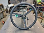
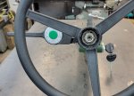
The new steering wheel is comfortable and the D shape is nice getting in and out. I used the horn and like that I retained the original horn button. The steering wheel adapter worked out perfectly for spacing the steering wheel. The shortened steering column coupled with the relocated directional switch and steering wheel position all seem to work together for over all feel. Nothing is jammed up together like the distance from the wheel to the directional lever or the lever to the light switch or the wheel to the dash. Very happy with the way it came out and all works together.

The steering wheel lock and ignition switch works like a charm. I like the feeling of security with the steering wheel locked when I walk away from it. Also the keyed ignition feel 100 times better than the dash mounted, aftermarket cheap key switch. The key is a real vehicle key not a file cabinet type key. The action of the switch feel positive and not soft like the other one. The location like a standard car steering column also just feels right. And lastly, it fits, works and looks like it belongs there and could have been OEM.

The rear view/dash camera system is not fully functional yet. There was an issue with the length of cable to the rear camera so I bought and extended cable and it wouldn't work with the supplied camera. I had to purchase a different "upgraded" camera and it is slightly larger than the original camera so I have to modify the mount I made. I hope to do that in the next week or 2. That said, the dashcam part pointing forward looked great and was easy to see in the "mirror" display. I suspect the rear will look equally as well. However the display beeps at me at varying rates for some reason and I can't figure out what it triggering it. It was borderline driving me crazy because I wasn't sure if it was the display or the transmission controller indicating an issue. Thankfully have it narrowed down to the display.

There is more but I haven't had a chance to use those systems yet, like the VIC-3. In general I am extremely happy with the outcome of all the modification. Things don't always go as planned or work as intended but so far I feel lucky, about 95% success rate. Just have to remount the rear camera.
 

springer1981

Well-known member
844
1,147
93
Location
Maine
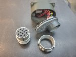
I haven't been working on the truck much but I have been enjoying it. In another thread (by Mogman) there was some discussion on how the stop lights work and a way to rewire them to add a little safety. I liked the idea and looked for a different way to implement the same basic changes. I wanted the changes to be made in the switch rather than in the wiring harness. I bought a new Three Lever Light Switch on ebay and then started to figure out how to take it apart. I don't want to destroy the case while opening it. The rear of the switch seems to be pressed in place and sealed shut. My first thought was using the connector plug to pull the back off. The threads on the connector plug are about 1.75" x 18 tpi. Turns out there are no common threads that size. I did find a surplus connector and I can use the "nut" from it. I have to make the rest of the tool now. I will get pictures when I work on taking it apart.

My latest version of the modification will work as follows.
Both stop light and Signal light circuits will be supplied with power from a switched power source via an unused connection "L" in picture below. All mods will be done in the switch with exception of adding 1 wire to switched power. No harness mods will be required.

The light switch operation would now be much more like what is found in a regular car or truck.
In the OFF position the Brake Lights, Directional, Horn and Reverse lights will all function when the truck is in the RUN position.
In the "Stop Light" position the marker lights, dash lights (subject to dimmer switch operation) and tail lights would come on.
In the "Service Drive" position the Headlights will come on if the Light/dimmer switch is left in one of the ON positions
The Blackout tail lights, stop lights and directional signals will not function when Blackout is selected but the Blackout driving light will function. The horn and the Reverse Lights (if present) will still function in Blackout.

Turn signal7.jpg
 

springer1981

Well-known member
844
1,147
93
Location
Maine
I bought the switch a couple of weeks ago and then had to figure out how to get it apart. Not knowing how it was put together and what to expect, I wanted to be careful with the disassembly so as to not damage it. Of course I tried to pull it apart by hand after I removed the silicone seal on the rear of it. It did not budge so I figured I would buy some sort of nut to fit the plug. By my best guess it would be something like 1.75" x 18 nut. Turns out there is no such thing so I bought a surplus wiring harness connector to use the nut. The idea is to use a spacer to the outside of the switch and use the nut to pull the back of the switch out. I could have just grabbed the threaded part of the switch with some sort of pliers but I didn't want to damage the threads, that made the nut a better solution.

Today I used a couple of spacer blocks and the nut to see if I could budge it before making some elaborate tools. I hold the bars on each side of the threads and twisted the nut by hand and in about 5 seconds it was coming apart. At that point I just pulled on the nut easily and it came apart the rest of the way. All in all it was far easier than I expected and now I know I could put a little piece of copper on the threads and use needle nose pliers and pull it apart.

Now that it is apart you can see the o-ring and just some residual silicone was holding it together. Based on the pictures of the old style switches, this should be pretty easy to modify. Still have to take it apart and see if I have to modify anything on the switch itself. More to come...

Switch1.jpg

Switch2.jpg
 
Last edited:

springer1981

Well-known member
844
1,147
93
Location
Maine
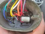
I took the switch apart the rest of the way so I could make sure it matched the schematic above. When I first started to check the wiring of the pins to the switch I kept getting lost quickly because I would chase a wire from the pin to the switch and it wouldn't go where I expected it to. I'd double check the pin location and it was totally wrong. I had to stop until I got a chance to take it apart where I could see the switch contacts to make sure I was in the correct place.

Now that I can see the contacts, I figured out the wiring is completely different than the wiring diagram and switch schematic. As I mentioned above, I purchased the mating connector to help disassemble the switch. I decided to check the wiring harness connector pins and compare them to the switch pins. They DON'T match!!! It only took a couple of second to see the pins are reversed. The wiring diagram and switch schematic actually represent the harness connector and NOT the switch connector.

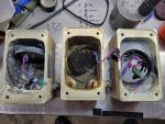
On the left is the wiring harness connector and the right is the back of the switch. You can see the pins match. The Red circles "A" pins and Green circled "C" pins are in the same locations. However when you flip the harness connector over to plug it into the switch, you see the "J" socket pin matches up to the "A" switch pin. The "A" socket pin would match up to the "J" switch pin. You can see that would also be the same for all the pins except the 2 in the middle "K" and "M".

I think the switch (right side) connector was put together wrong. My guess is those pin letters are suppose to be on the solder side and not the pin side. If it was reversed so the lettering was on the solder side, the connectors would then match.

Switch4.jpg

Also, I was somewhat expecting the switch contacts pop out and be a mess parts however it stayed together neatly and should make for easy reassembly. I only have to make 1 modification to a contact and I should be able to do that without disassembling the switch any further.

Switch3.jpg
 

Mogman

Moderator
Staff member
Moderator
Steel Soldiers Supporter
5,815
8,081
113
Location
Papalote, TX
Interesting, it is not a "mirror" image as it should be just the same "image"
BOY that is a GOOD discovery on your part as it may save someone allot of grief, definitely stuffed into my memory banks!!
 

springer1981

Well-known member
844
1,147
93
Location
Maine
I think the switch (right side) connector was put together wrong. My guess is those pin letters are suppose to be on the solder side and not the pin side. If it was reversed so the lettering was on the solder side, the connectors would then match.
So I wrote the above sentence after I took the pictures and figure it all out. I forgot the solder side IS labeled as well. The switch connector isn't assembled wrong.
 

springer1981

Well-known member
844
1,147
93
Location
Maine
The connector should be correct on both sides yes???
I've never seen a matching male and female connector where the pins didn't match each other when connected together. The wiring diagram with one set of pins listed represents that. In other words, both sets of pins are expected to match the wiring diagram or they wouldn't have drawn it that way.

I just finished the final drawing of the modified switch. I added the pins on both connectors so I would know what gets connected where. Now I want to see if my old original light switch is the same way. I will find out when I go to change it out.

The wire colors now match what it in my switch. The colors of the letters for the connector pins are the original wire colors that went to that pin. For example, Pin N is a red wire. It is going to go to Pin A (originally a yellow wire) and to Pin J (originally a white wire). The yellow wire that originally went to Pin A is now going to Pin B (originally green). Pin C is a green wire with a red stripe and denoted on the letter C is a little Red.

switchwiring.jpg

Assuming the pins and colors all match my diagram, these are the modification instructions.

Remove Green wire from light switch post H and pin B

Remove Yellow wire from pin A and solder to pin B

Remove white wire from pin J and switch post A

Unsolder red wire from dimmer switch post L

Solder red wire from pin N to pin A and pin J

Remove black wire from light switch post N and pin L

Remove purple wire from light switch post E and pin D

Add light switch contact extending post C one position to the center
 
Last edited:

springer1981

Well-known member
844
1,147
93
Location
Maine
I was asked about the TPS sensor I used in my 4L80 conversion so I took a couple pictures.

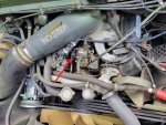
I used a Standard TH160 TPS sensor that is a very common GM TPS sensor. For reference of the location, the first picture shows where the TPS sensor gets located. The connector just above the arrow is the TPS sensor connector and wiring that I ran into the cab to the Quick4 TCU.

TPS1.jpg

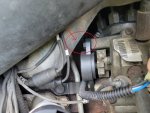
You must first remove the Fan Cutoff switch and cam from the shaft. Keep the pin that held the cam on the shaft. One of the bolts is a little too long to remove because it hits the intake manifold. I used a bur on an air grinder to take the rough casting edge off the side of the manifold to make room for the bolt to come all the way out. I could have easily done it with a file also. Bolt in circle and filed edge pointed to by arrow.

TPS2.jpg

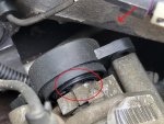
In the picture below the shaft is circled. Before putting the TPS on you must put the pin back in the shaft. The pin actuates the TPS. The TPS mounts have some adjustment too them. I adjusted it until it just barely applied pressure to the rotation of the TPS. This makes it so it will start reading as soon as you apply throttle. If it was loose then the throttle could be depressed some before it started to read. It was simply a "feel" thing when turning by hand. The Arrow again shows the filed edge for bolt removal and installation clearance.

TPS3.jpg
 
Last edited:

Mogman

Moderator
Staff member
Moderator
Steel Soldiers Supporter
5,815
8,081
113
Location
Papalote, TX
You can take a hot knife (I used an old knife heated with a torch) to "cut" the old kickdown cam down to the exposed pin, then simply insert a screwdriver and twist, the cam will split on the other side where the non exposed pin is leaving the pin in place and it being not necessary to try and beat the pin out of the shaft.
 

springer1981

Well-known member
844
1,147
93
Location
Maine
I regularly look for anything related to the Avenger platform for my truck. Rarely does anything come up and even more rare is it being useful to me. As I'm sure you are all aware, they don't really like people having missile launchers so finding anything related is difficult.

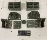
I found Avenger hard top mounts for the roof and rear panel. I don't need mounts but there was a data plate with the mounts and it had a picture of the HMMWV with the Avenger unit and gave weight and dimension information. On the inside roof, above my driver door, I am missing 2 data plates. They were removed when it was demilled and I didn't know what was on them, just that they were missing.

I came across these mounts listed on epay and then had to weigh the cost ($260) just to get the data plate. It took about 2 minutes to rationalize the chances of finding another one, so I bought the lot. I followed up the purchase with a note asking the seller to take extra precaution to protect the data plate in shipping.

Data1.jpg

The seller replied asking if I was putting an Avenger together and he mentioned he previously had owned 3 of them.

I told him I have one that was missing the 2 data plates and I bought his parts just for the data plate in the picture. I also mentioned I didn't even know what was on the missing data plate because I had never seen them before. Side note, I scoured the internet trying to find pictures of the data plates to no avail.

The seller replied "I found the other plate too so I threw it in for free for you".

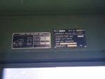
Sure enough it was the other missing data plate. That data plate is the identification tag for the "Avenger Fire Unit". Of all the stuff I have done to my M998 Avenger, that was the best $260 I have spent.

Then I had to find the correct rivets (twice lol) but mounted them this morning!!

Data2.jpg


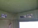
And here is the complete set installed where they belong. I never expected to find them and can't thank the ebay seller enough!

Data3.jpg
 
Last edited:

Mullaney

Well-known member
Steel Soldiers Supporter
Supporting Vendor
7,252
18,811
113
Location
Charlotte NC
I regularly look for anything related to the Avenger platform for my truck. Rarely does anything come up and even more rare is it being useful to me. As I'm sure you are all aware, they don't really like people having missile launchers so finding anything related is difficult.

I found Avenger hard top mounts for the roof and rear panel. I don't need mounts but there was a data plate with the mounts and it had a picture of the HMMWV with the Avenger unit and gave weight and dimension information. On the inside roof, above my driver door, I am missing 2 data plates. They were removed when it was demilled and I didn't know what was on them, just that they were missing.

I came across these mounts listed on epay and then had to weigh the cost ($260) just to get the data plate. It took about 2 minutes to rationalize the chances of finding another one, so I bought the lot. I followed up the purchase with a note asking the seller to take extra precaution to protect the data plate in shipping.

View attachment 883724

The seller replied asking if I was putting an Avenger together and he mentioned he previously had owned 3 of them.

I told him I have one that was missing the 2 data plates and I bought his parts just for the data plate in the picture. I also mentioned I didn't even know what was on the missing data plate because I had never seen them before. Side note, I scoured the internet trying to find pictures of the data plates to no avail.

The seller replied "I found the other plate too so I threw it in for free for you".

Sure enough it was the other missing data plate. That data plate is the identification tag for the "Avenger Fire Unit". Of all the stuff I have done to my M998 Avenger, that was the best $260 I have spent.

Then I had to find the correct rivets (twice lol) but mounted them this morning!!

View attachment 883725


And here is the complete set installed where they belong. I never expected to find them and can't thank the ebay seller enough!

View attachment 883726
.
Pretty dang amazing that you found those dataplates...
AND that the seller was willing to help with the second plate!
 

springer1981

Well-known member
844
1,147
93
Location
Maine
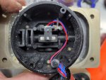
It seems when it comes to HMMWV's you can never have enough projects. I bought some more inoperable turret joysticks to see if I can get one working. It starts with disassembly and inspection. There are 2 basic parts, a sensor and a magnet. The common cause of issues seems to be water in the joystick. All 3 of these were full of water despite rubber gaskets, silicon and o-rings on the screws. I can tell you unequivocally they are NOT waterproof even with all the attempts to seal them. Here's a picture of the sensor and magnet.

Joystick1.jpg

The first one I opened, though fully encased with a silicon rubber compound, dripped water out of it. The second one didn't have the compound in it and was the first time I have opened on that didn't and I wasn't ready for it. All the previous ones had it and are a bit of a chore to get apart. Using the same method to take this one apart resulted in a lap full of old rusty water. It was full of water and the internals of the joystick controller were as well. The magnet was rusted beyond salvageable. That joystick is likely a complete waste. The third joystick was half full of water and white stuff from the aluminum of connector.

Joystick2.jpg

All and all I might have 2 salvageable sensors and 2 good magnet. The sensor board is simple in design however the hall effect sensor itself is a pretty complicated little device that is programable. Although you could easily buy a replacement hall effect, you could not program it easily or at least I can not. Next I'll clean up the boards the best I can and test them.

Joystick3.jpg
 

springer1981

Well-known member
844
1,147
93
Location
Maine
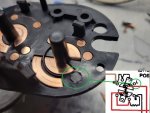
I rewired my light switch today. Part of the job was moving a copper contact that I am no longer using to a place where I needed a new contact. Part of the dimmer switch (post L on the diagram) is no longer used so I removed it. I had to fill the hole so the rotating contact does get stuck in it. I used a piece of zip tie and a little superglue. The GREEN circle shows the contact I removed.

switch5.jpg

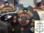
In the switch diagram in the lower right corner (1) it shows a connection that didn't exist, indicated by the red wire. The GREEN circle (2) shows where it has to be installed. I started by drilling a 1/8" hole threw the plastic. Then using a 3/16" drill I carefully added a counter sink (3). Then I took the copper contact I removed above and inserted it in the hole (4). I then attached it to the copper contact pad to the right of it in the pictures below. I attached it on the back side. This contact is what allows brake lights, horn and directionals to work without having to turn on the lights.

switch6.jpg
 

springer1981

Well-known member
844
1,147
93
Location
Maine
The truck ran great all year. No leaks, no issues and starts right up. We have some snow coming (not much) and that signals to me it's time to put the truck in the garage for the winter. Not that it can't take the winter but so I can keep working on it and moving the project forward.

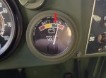
My garage is less than 1 mile from my house and first thing I notice is the volt meter higher than normal. It has never been anywhere except on the white line in the green area (Red Arrow). Today it's running in the Red area!! I parked the truck for a few minutes and when I came back, antifreeze under the truck!! Leaking like a Siv.

I drove the last mile of the year and all hell breaks loose! (ok not that bad but....WTF) :confused:

Volts.jpg
 

springer1981

Well-known member
844
1,147
93
Location
Maine
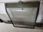
As I stated in a previous post about the Avenger data plates, I keep an eye out for Avenger related items. It's a rare occasion that anything comes up. Recently I came across another Avenger part, the hatch (official term unknown by me). I've toyed with the idea of building a mock Avenger fire unit since I can't get a real one. What better start to a mock unit than a real hatch? Worst case it makes a great conversation starter.

Well it arrived today and I was pleasantly surprised with its condition. Maybe someday it will be attached in its proper location on my truck.

Cover.jpg


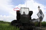
Reference of where it goes on the real deal.
Cover2.jpg
 
Top
AdBlock Detected

We get it, advertisements are annoying!

Sure, ad-blocking software does a great job at blocking ads, but it also blocks useful features of our website like our supporting vendors. Their ads help keep Steel Soldiers going. Please consider disabling your ad blockers for the site. Thanks!

I've Disabled AdBlock
No Thanks