• Steel Soldiers now has a few new forums, read more about it at: New Munitions Forums!

  • Microsoft MSN, Live, Hotmail, Outlook email users may not be receiving emails. We are working to resolve this issue. Please add support@steelsoldiers.com to your trusted contacts.

MEP-531a Aftermarket regulator/project

Skyhawk13205

Well-known member
158
270
63
Location
Alaska
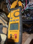
Hello, first time posting on the generator forum. I have 2 MEP-531a generators, I could not get either of them to work, I found that the VR does not pass the lightbulb test and I can’t get to power on. Both VR are swelled and once is cracked. I found an aftermarket VR called a EA350, I could not get to work until I disconnected the exciter winding then put 12v on positive lead of exciter and negative to the neutral momentarily. Voltage eventually stabilized at 120 but I have to adjust the voltage adjust on the VR. I load tested for an hour with a heat gun measuring 14amps. I am running with the exciter field disconnected and only using for flashing on initial power on, how will that effect the generator operation.

I have attached manuals for OEM VR 63-4 and aftermarket EA350
 

Attachments

Skyhawk13205

Well-known member
158
270
63
Location
Alaska
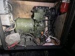
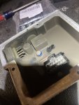
My project seems to have blown something up, I installed the generator in my camper to run the AC buss. I basically gutted the MEP-531a electronics and moved them into a control panel in my camper. I had to modify quite a bit to get it to work, the ops check was ok the generator was able to come on line and run a load. The issue is after I ran my generator I noticed my heater would not work, I found the ECU was cooked, it looks like the ground connector is burnt. My theory is the exciter somehow caused a voltage spike or backfeed onto the DC buss. It appears none of the other devices are damaged just the Espar heater ECU. If my theory is valid I think the solution would be to either isolate the field exciter with a double pole switch or use an isolated power supply.
 

Attachments

peapvp

Well-known member
Steel Soldiers Supporter
1,119
1,247
113
Location
Basehor, KS
My project seems to have blown something up, I installed the generator in my camper to run the AC buss. I basically gutted the MEP-531a electronics and moved them into a control panel in my camper. I had to modify quite a bit to get it to work, the ops check was ok the generator was able to come on line and run a load. The issue is after I ran my generator I noticed my heater would not work, I found the ECU was cooked, it looks like the ground connector is burnt. My theory is the exciter somehow caused a voltage spike or backfeed onto the DC buss. It appears none of the other devices are damaged just the Espar heater ECU. If my theory is valid I think the solution would be to either isolate the field exciter with a double pole switch or use an isolated power supply.
You are lucky that you are still alive and can post your findings.

One day someone here is going to kill him / herself with these generators

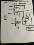
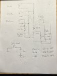
There is several things wrong with your wiring diagram.

First, your exciter coil is connected directly to 24 VDC at all times

Second, your exciter switch basically shorts your first battery, which is connected to ground, every time you activate the switch. I am sure your switch blew up the first time you used it.

I would stop here and consult with a local generator expert before further proceeding
 

Skyhawk13205

Well-known member
158
270
63
Location
Alaska
You are lucky that you are still alive and can post your findings.

One day someone here is going to kill him / herself with these generators

There is several things wrong with your wiring diagram.

First, your exciter coil is connected directly to 24 VDC at all times

Second, your exciter switch basically shorts your first battery, which is connected to ground, every time you activate the switch. I am sure your switch blew up the first time you used it.

I would stop here and consult with a local generator expert before further proceeding
If I die from this project I will make sure to post the details.

thanks for noticing the issue with the grounds

I didn’t see the issue with the grounds when I drew up that schematic, the grounds are isolated. the DC and AC buss ground check has no continuity between the two. I was debating leaving the neutral unbounded to ground but i didn’t want the possibility of my metal surfaces being electrified. The regulator exciter was fused with a 1 amp fuse. The field was fused with a 1amp fuse. The max field voltage is 18 v before the fuse trips thus tripping the field. I took some precautions in the wiring to prevent an accident.
 

peapvp

Well-known member
Steel Soldiers Supporter
1,119
1,247
113
Location
Basehor, KS
@Skyhawk13205
Then if I understand you correctly, you actually have this wired up like this:

IMG_9801.jpeg

The exciter coil is then powered by the top battery in your diagram and gets about 12V when you close your exciter switch which is most likely a momentary push button type switch.

Did you leave the one leg of the exciter coil connected to the common legs of Genset coils which are basically the Neutral in this system and which is not grounded to chassis and or earth ground?

This is how I understand your post #6

please correct me if I am wrong
 

Skyhawk13205

Well-known member
158
270
63
Location
Alaska
@Skyhawk13205
Then if I understand you correctly, you actually have this wired up like this:

View attachment 918011

The exciter coil is then powered by the top battery in your diagram and gets about 12V when you close your exciter switch which is most likely a momentary push button type switch.

Did you leave the one leg of the exciter coil connected to the common legs of Genset coils which are basically the Neutral in this system and which is not grounded to chassis and or earth ground?

This is how I understand your post #6

please correct me if I am wrong
yes, that is basically how my wiring is. The exciter windings are part of the stator windings and terminate on the N side of the power windings. I would have liked to separate the exciter from the power but it is not possible without taking the stator apart.

you were right about almost killing myself. I didn’t think about how much voltage the exciter field would generate when the field is powered. I measured about 32-70vdc on the exciter field. It was creating about a 90vdc potential between N to DC ground. I had a 1amp fuse but that is still enough to Kill someone especially with high voltage DC.

I think I figured out how I blew up my espar ECU, I paralleled a 70vdc on the 12v battery momentarily when I used the exciter flash, I had trouble with the exciter field flash and getting the proper output, and I cycled multiple times while the field was powered by the regulator. Even though the gen was unloaded the field was carrying a 30-70vdc potential and used the ECU as a return path when I cycled the exciter flash. It was an expensive mistake and I am lucky that nothing else was damaged and no one was hurt.

I work on power generation systems for turbine engines up to 90kva and it is easy to forget how dangerous electrical power is when you are working on something so small, but dead is dead from a 30kw arc flash to a 1amp heart jump stop.

next is to find a solution for the exciter flash, the only solution I can think of is to have a separate battery to flash the exciter. I do not think it needs much power, I am thinking of just using a 6v battery.
 

peapvp

Well-known member
Steel Soldiers Supporter
1,119
1,247
113
Location
Basehor, KS
@Skyhawk13205
Luck be a Lady,

what is your measured DC Resistance of the exciter and field coil, without anything connected to either one ?
 

Skyhawk13205

Well-known member
158
270
63
Location
Alaska
Spent some more time re designing. Disconnected my exciter system from the DC buss, I found out that the exciter was backfeeding line voltage onto the dc bus and using my Espar ecu as a ground path I found the Espar heater had a chassis ground of 18k ohms when the ecu was connected. I combined all my grounds so the DC and AC buss have a common now. I used a 9v batt as the exciter voltage. I have to run more tests to see if the exciter is backfeeding or not but hopefully I can be done with this project.

I have 2 safety’s in the system, the 2amp regulator breaker will trip at 110% load or 16 amps, the breaker is built to trip at 15 amps. If I trip fuses frequently I will up to 3amps. The exciter is protected from backfeeding at .25 amps so max of 30w before it trips. I used all fast blow fuses5A08C634-AAFB-4F84-A49C-6EF961AB00AD.jpeg
 

peapvp

Well-known member
Steel Soldiers Supporter
1,119
1,247
113
Location
Basehor, KS
Spent some more time re designing. Disconnected my exciter system from the DC buss, I found out that the exciter was backfeeding line voltage onto the dc bus and using my Espar ecu as a ground path I found the Espar heater had a chassis ground of 18k ohms when the ecu was connected. I combined all my grounds so the DC and AC buss have a common now. I used a 9v batt as the exciter voltage. I have to run more tests to see if the exciter is backfeeding or not but hopefully I can be done with this project.

I have 2 safety’s in the system, the 2amp regulator breaker will trip at 110% load or 16 amps, the breaker is built to trip at 15 amps. If I trip fuses frequently I will up to 3amps. The exciter is protected from backfeeding at .25 amps so max of 30w before it trips. I used all fast blow fusesView attachment 919082
Your wiring diagram looks ok to me. I would move the #4 Terminal with the fuse to the other side of the 15 Amp Breaker. This way your field wont collapse when the 15 Amp Breaker trips on the load side.

The backfeeding of the exciter coil should not pose a problem since one leg is Neutral / Ground. The voltage built up will be on the switch side which is open and is therefor insulated from the 9V battery and everything else.
 

Skyhawk13205

Well-known member
158
270
63
Location
Alaska
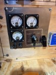
Ran a test today, couple of hang ups, the 100w field resistor is to low, it got so hot I burnt myself on it and it melted some insulation on a wire touching it. Also I am getting a 120hz on my analog gauge vs 60hz on my multimeter. Generator worked great, provided consistent power and met the demand that was requested of it. I am thinking of upsizing the resistor to a 500w.
C363A9DD-F713-4936-9053-8961941ED47B.jpegE58296C3-3071-4B6B-9703-47422B7EA73B.jpeg
 

peapvp

Well-known member
Steel Soldiers Supporter
1,119
1,247
113
Location
Basehor, KS
Ran a test today, couple of hang ups, the 100w field resistor is to low, it got so hot I burnt myself on it and it melted some insulation on a wire touching it. Also I am getting a 120hz on my analog gauge vs 60hz on my multimeter. Generator worked great, provided consistent power and met the demand that was requested of it. I am thinking of upsizing the resistor to a 500w.
View attachment 919121View attachment 919122
That’s what power resistors do, they get hot. That’s why they are called power resistors. It’s basically a heater.
Mount these type of resistors on a 16ga or thicker sheet metal and make sure the location of this puppy is well ventilated, far away from anything flammable, gas or diesel and wiring.
You may have to use a cooling fan
 

peapvp

Well-known member
Steel Soldiers Supporter
1,119
1,247
113
Location
Basehor, KS
Ran a test today, couple of hang ups, the 100w field resistor is to low, it got so hot I burnt myself on it and it melted some insulation on a wire touching it. Also I am getting a 120hz on my analog gauge vs 60hz on my multimeter. Generator worked great, provided consistent power and met the demand that was requested of it. I am thinking of upsizing the resistor to a 500w.
View attachment 919121View attachment 919122
not sure of what to make out of your analog frequency gauge.
 

peapvp

Well-known member
Steel Soldiers Supporter
1,119
1,247
113
Location
Basehor, KS
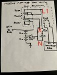
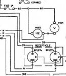
I am not 100% sure if this is your wiring diagram, the Volt Gauge and Frequency gauge are connected in Parallel to L1 and N which would be 120VAC

In this case your Frequency Gauge is toast

IMG_9931.jpeg
 

peapvp

Well-known member
Steel Soldiers Supporter
1,119
1,247
113
Location
Basehor, KS
Ran a test today, couple of hang ups, the 100w field resistor is to low, it got so hot I burnt myself on it and it melted some insulation on a wire touching it. Also I am getting a 120hz on my analog gauge vs 60hz on my multimeter. Generator worked great, provided consistent power and met the demand that was requested of it. I am thinking of upsizing the resistor to a 500w.
View attachment 919121View attachment 919122
And one last post in reply to your thoughts as to upgrading to a 500W resistor

I read all the previous posts and in post #1 you posted two data sheets for two different AVR’s. A VR6e3-4A/UL and a EA350

which one do you have actually installed?
 
Top
AdBlock Detected

We get it, advertisements are annoying!

Sure, ad-blocking software does a great job at blocking ads, but it also blocks useful features of our website like our supporting vendors. Their ads help keep Steel Soldiers going. Please consider disabling your ad blockers for the site. Thanks!

I've Disabled AdBlock
No Thanks