@Skyhawk13205
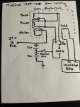
Then if I understand you correctly, you actually have this wired up like this:
View attachment 918011
The exciter coil is then powered by the top battery in your diagram and gets about 12V when you close your exciter switch which is most likely a momentary push button type switch.
Did you leave the one leg of the exciter coil connected to the common legs of Genset coils which are basically the Neutral in this system and which is not grounded to chassis and or earth ground?
This is how I understand your post #6
please correct me if I am wrong
yes, that is basically how my wiring is. The exciter windings are part of the stator windings and terminate on the N side of the power windings. I would have liked to separate the exciter from the power but it is not possible without taking the stator apart.
you were right about almost killing myself. I didn’t think about how much voltage the exciter field would generate when the field is powered. I measured about 32-70vdc on the exciter field. It was creating about a 90vdc potential between N to DC ground. I had a 1amp fuse but that is still enough to Kill someone especially with high voltage DC.
I think I figured out how I blew up my espar ECU, I paralleled a 70vdc on the 12v battery momentarily when I used the exciter flash, I had trouble with the exciter field flash and getting the proper output, and I cycled multiple times while the field was powered by the regulator. Even though the gen was unloaded the field was carrying a 30-70vdc potential and used the ECU as a return path when I cycled the exciter flash. It was an expensive mistake and I am lucky that nothing else was damaged and no one was hurt.
I work on power generation systems for turbine engines up to 90kva and it is easy to forget how dangerous electrical power is when you are working on something so small, but dead is dead from a 30kw arc flash to a 1amp heart jump stop.
next is to find a solution for the exciter flash, the only solution I can think of is to have a separate battery to flash the exciter. I do not think it needs much power, I am thinking of just using a 6v battery.