ErichLessing
New member
- 17
- 7
- 3
- Location
- Texas
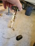
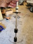
I have a MEP 805A genset that has 293 hours post level 2 reset. Installed a new pair of batteries and main panel was dead. I discovered both wires at CR1 were detached from the lugs. I replaced the CR1 Diode and re-soldered both wires to the lugs. Main panel now has power but I have a "no fuel" indicator light. Verified tank is 1/4 full with new fuel. Verified Aux fuel pump is running when master switch is set to "Aux Fuel Prime" position. No fuel pump runs when master switch is set to "Prime/Run" position. I set master switch to aux fuel prime for about 5 minutes and then checked fuel/water separator which had fuel under the top cap. I broke the fuel supply line at the injector pump and drops of fuel came out. I removed one injector fuel line from the inj. pump and it was dry, no fuel. Engine would crank at first until the NO FUEL indicator light came on. I could clear the fault and repeat a couple of times but now, I get NO CRANK even after clearing the fault. Engine will crank in "Dead Crank" mode. Engine has not made any indication of trying to run throughout this process. I have not messed with the MPU and don't know how to use my multi-meter to check voltage on it. "I are welder", lol not generator mechanic soooo I give up! Does anyone know of a service company in North East Texas that can get this thing running?
Thanks!
Thanks!