• Steel Soldiers now has a few new forums, read more about it at: New Munitions Forums!

  • Microsoft MSN, Live, Hotmail, Outlook email users may not be receiving emails. We are working to resolve this issue. Please add support@steelsoldiers.com to your trusted contacts.

MEP 805A Fuel / Start Problems - Repair Service in North East Texas???

ErichLessing

New member
16
6
3
Location
Texas
I have a MEP 805A genset that has 293 hours post level 2 reset. Installed a new pair of batteries and main panel was dead. I discovered both wires at CR1 were detached from the lugs. I replaced the CR1 Diode and re-soldered both wires to the lugs. Main panel now has power but I have a "no fuel" indicator light. Verified tank is 1/4 full with new fuel. Verified Aux fuel pump is running when master switch is set to "Aux Fuel Prime" position. No fuel pump runs when master switch is set to "Prime/Run" position. I set master switch to aux fuel prime for about 5 minutes and then checked fuel/water separator which had fuel under the top cap. I broke the fuel supply line at the injector pump and drops of fuel came out. I removed one injector fuel line from the inj. pump and it was dry, no fuel. Engine would crank at first until the NO FUEL indicator light came on. I could clear the fault and repeat a couple of times but now, I get NO CRANK even after clearing the fault. Engine will crank in "Dead Crank" mode. Engine has not made any indication of trying to run throughout this process. I have not messed with the MPU and don't know how to use my multi-meter to check voltage on it. "I are welder", lol not generator mechanic soooo I give up! Does anyone know of a service company in North East Texas that can get this thing running?
Thanks!
 

Guyfang

Moderator
Staff member
Moderator
16,912
24,520
113
Location
Burgkunstadt, Germany
The No fuel fault will not allow you to try and start the gen set. Pull out the fuel tank float assembly. See if the floats are stuck, are there, not damaged. As long as that signal goes to the Fault indicator, it wont start.

Have you seen this gen set run right? Is it new to you? Have you down loaded the TM's and read the troubleshooting?
Have you looked into the tank with a flash light to see if its a swamp?


I have a MEP 805A genset that has 293 hours post level 2 reset. Installed a new pair of batteries and main panel was dead. I discovered both wires at CR1 were detached from the lugs. I replaced the CR1 Diode and re-soldered both wires to the lugs. Main panel now has power but I have a "no fuel" indicator light. Verified tank is 1/4 full with new fuel. Verified Aux fuel pump is running when master switch is set to "Aux Fuel Prime" position. No fuel pump runs when master switch is set to "Prime/Run" position. (What pump would run in Prime/Run position?) I set master switch to aux fuel prime (The only thing you are doing here nothing. The Aux system only turns on when the fuel float "Need to fill the tank" drops low enough to tell the pump to refill the tank. Nothing more.) for about 5 minutes and then checked fuel/water separator which had fuel under the top cap. I broke the fuel supply line at the injector pump and drops of fuel came out. I removed one injector fuel line from the inj. pump and it was dry, no fuel. Engine would crank at first until the NO FUEL indicator light came on. I could clear the fault and repeat a couple of times but now, I get NO CRANK even after clearing the fault. Engine will crank in "Dead Crank" mode. (Of course. The S-10 is independent of the normal safety switches. And, the S-10 will not allow you to start the engine. Only turn the engine over.) Engine has not made any indication of trying to run throughout this process. I have not messed with the MPU and don't know how to use my multi-meter to check voltage on it. "I are welder", lol not generator mechanic soooo I give up! Does anyone know of a service company in North East Texas that can get this thing running?
Thanks!

Even a welder can troubleshoot this problem. Before you do anything more, try this. Unplug the Fault indicator. Then try and start the engine. If it starts, shut it down, and the problem is maybe the float. We can walk you through that troubleshooting. Let us know what happens.
 

ErichLessing

New member
16
6
3
Location
Texas
The No fuel fault will not allow you to try and start the gen set. Pull out the fuel tank float assembly. See if the floats are stuck, are there, not damaged. As long as that signal goes to the Fault indicator, it wont start.

Have you seen this gen set run right? Is it new to you? Have you down loaded the TM's and read the troubleshooting?
Have you looked into the tank with a flash light to see if its a swamp?


I have a MEP 805A genset that has 293 hours post level 2 reset. Installed a new pair of batteries and main panel was dead. I discovered both wires at CR1 were detached from the lugs. I replaced the CR1 Diode and re-soldered both wires to the lugs. Main panel now has power but I have a "no fuel" indicator light. Verified tank is 1/4 full with new fuel. Verified Aux fuel pump is running when master switch is set to "Aux Fuel Prime" position. No fuel pump runs when master switch is set to "Prime/Run" position. (What pump would run in Prime/Run position?) I set master switch to aux fuel prime (The only thing you are doing here nothing. The Aux system only turns on when the fuel float "Need to fill the tank" drops low enough to tell the pump to refill the tank. Nothing more.) for about 5 minutes and then checked fuel/water separator which had fuel under the top cap. I broke the fuel supply line at the injector pump and drops of fuel came out. I removed one injector fuel line from the inj. pump and it was dry, no fuel. Engine would crank at first until the NO FUEL indicator light came on. I could clear the fault and repeat a couple of times but now, I get NO CRANK even after clearing the fault. Engine will crank in "Dead Crank" mode. (Of course. The S-10 is independent of the normal safety switches. And, the S-10 will not allow you to start the engine. Only turn the engine over.) Engine has not made any indication of trying to run throughout this process. I have not messed with the MPU and don't know how to use my multi-meter to check voltage on it. "I are welder", lol not generator mechanic soooo I give up! Does anyone know of a service company in North East Texas that can get this thing running?
Thanks!

Even a welder can troubleshoot this problem. Before you do anything more, try this. Unplug the Fault indicator. Then try and start the engine. If it starts, shut it down, and the problem is maybe the float. We can walk you through that troubleshooting. Let us know what happens.
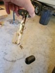
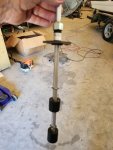
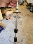
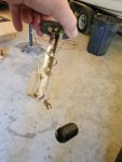
Thank You for the help. I have attached 2 pictures and apologize if I named them incorrectly. 1. The fuel tank level indicator was free functioning and the ohms changed slightly when I moved the float arm up and down. 2. The other twin float assembly was also not stuck but it showed no ohm's at all on my multi-meter when I placed the probes on the red and black pins. 3. The fuel tank interior is clean. 4. This is the first attempt I have made to get the generator running since purchasing it on GovPlanet. 5. After reinstalling both float assemblies, I unplugged the Fault Indicator and attempted to start the generator. She fired right up after about 10 seconds of cranking. I shut it down after 3 seconds. I plugged-in the Fault Indicator and now have a constant "Overspeed" fault light that will not clear. 6. While trying to clear the Overspeed fault light I heard a sizzle and watched CR-1 Diode smoke. I had the battery charger hooked up to the battery while I started the unit, could that be the cause of CR-1 burn-out? 7. Unit will not crank over with the Fault Indicator plugged back in. What now?
 

Attachments

Guyfang

Moderator
Staff member
Moderator
16,912
24,520
113
Location
Burgkunstadt, Germany
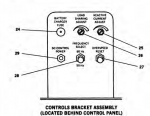
It might not hurt to sit down and read the TM 9-6115-644-10 Operators manual. Below is a picture of the S16 (Over Speed reset switch). Its inside the control panel.

1720554941985.png

I do not know if the CR1 burned up because of the battery charger. BUT, did you, when you replaced CR1, put it back in, in the right direction? Because if you didnt, that could be why it burnt up. Replace the CR1.

As long as the A2, (Fault Indicator) is hooked up and the over speed reset is not pushed up, the set will not turn over. Again, you need to read the book a little. You need to know what happens, when, and how. So after resetting the over speed fault, it will turn over.


1720555423467.png
Test the FL1 & FL2 (float switch) IAW the -24 TM.
TESTING
1. Shut down generator set.
2. Remove low fuel level/auxiliary fuel pump float switch (Removal).
3. Position float switch in vertical position, similar to position as installed in fuel tank.
4. For the top float, set multimeter for ohms and connect positive lead to pin 2 and negative lead to pin 1 of float
switch electrical connector.

5. With upper or lower float moving toward the down position, multimeter should indicate continuity 1/4-inch
before float reaches the down position.
6. Move upper float to full up position. Multimeter should indicate open circuit.
7. Disconnect multimeter leads from pins 1 and 2. To check lower float, connect positive lead to pin 3 and
negative lead to pin 4 of electrical connector.

8. Repeat Steps 5 and 6, except with lower float.
9. Replace low fuel level/auxiliary fuel pump float switch if indications are other than above.
10. Install low fuel level/auxiliary fuel pump float switch (Installation).

HIGHLIGHTED in yellow, is very important. This could be why you got no ohms reading.

1720555620225.png
This is the MT5, (Fuel tank level sender). The only thing it does is move the M5 (Fuel tank level meter). Put it back in.

Recap.
1. Replace the CR1
2. Reset the S16
3. Re-Test the the FL1 & FL2 switch IAW the -24 TM. If indeed the switch shows no opening and closing action, thats the problem that shows as "LOW FUEL on the A2. To whit, FL1 is the switch that will not net you start the set when you have a LOW fuel light on the A2.

1720556265119.png
So you understand the relation of the components to function.
 

ErichLessing

New member
16
6
3
Location
Texas
It might not hurt to sit down and read the TM 9-6115-644-10 Operators manual. Below is a picture of the S16 (Over Speed reset switch). Its inside the control panel.

View attachment 927468

I do not know if the CR1 burned up because of the battery charger. BUT, did you, when you replaced CR1, put it back in, in the right direction? Because if you didnt, that could be why it burnt up. Replace the CR1.

As long as the A2, (Fault Indicator) is hooked up and the over speed reset is not pushed up, the set will not turn over. Again, you need to read the book a little. You need to know what happens, when, and how. So after resetting the over speed fault, it will turn over.


View attachment 927469
Test the FL1 & FL2 (float switch) IAW the -24 TM.
TESTING
1. Shut down generator set.
2. Remove low fuel level/auxiliary fuel pump float switch (Removal).
3. Position float switch in vertical position, similar to position as installed in fuel tank.
4. For the top float, set multimeter for ohms and connect positive lead to pin 2 and negative lead to pin 1 of float
switch electrical connector.

5. With upper or lower float moving toward the down position, multimeter should indicate continuity 1/4-inch
before float reaches the down position.
6. Move upper float to full up position. Multimeter should indicate open circuit.
7. Disconnect multimeter leads from pins 1 and 2. To check lower float, connect positive lead to pin 3 and
negative lead to pin 4 of electrical connector.

8. Repeat Steps 5 and 6, except with lower float.
9. Replace low fuel level/auxiliary fuel pump float switch if indications are other than above.
10. Install low fuel level/auxiliary fuel pump float switch (Installation).

HIGHLIGHTED in yellow, is very important. This could be why you got no ohms reading.

View attachment 927470
This is the MT5, (Fuel tank level sender). The only thing it does is move the M5 (Fuel tank level meter). Put it back in.

Recap.
1. Replace the CR1
2. Reset the S16
3. Re-Test the the FL1 & FL2 switch IAW the -24 TM. If indeed the switch shows no opening and closing action, thats the problem that shows as "LOW FUEL on the A2. To whit, FL1 is the switch that will not net you start the set when you have a LOW fuel light on the A2.

View attachment 927471
So you understand the relation of the components to function.
Guyfang, Thank you for the help! I downloaded all the TM's and will start studying. Hopefully this unit will make power soon!
 

ErichLessing

New member
16
6
3
Location
Texas
Guyfang, Thank you for the help! I downloaded all the TM's and will start studying. Hopefully this unit will make power soon!
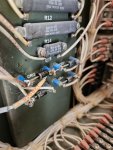
CR1 problem is persisting. I printed out the 644-10 initial adjustments before use and self test procedure. After resetting the Overspeed Reset switch (Fault Panel still plugged in) I placed the Master Switch in the Prime /Run position and was about to test the malfunction indicator panel when the S-17-1 162A wire soldered to the left plastic CR1 terminal lug started smoking. WTH?? it gets hot enough to melt the solder. CR-1 is the Battery Reverse Diode. I checked the battery wiring per the diagram on the door panel AGAIN and they are installed properly. I checked voltage at the starter - 20 volts. I checked voltage at the battery's - 24v. I checked the FO-2 wiring diagram of TM644-24 and it appears that I have the wires oriented and soldered to the plastic lug terminals properly. I'm at a loss as to what could be causing this problem. I have a feeling this is why the Mil unit DRMO'd this generator because the CR-1 wires were melted off of the CR-1 diode terminals when I bought the unit.
This generator is sitting in my shop and does NOT have a ground rod in the dirt, could the fact that its not grounded be causing the CR-1 melt down? The machine has run 3 seconds so far... Also, could I have installed batteries with too much cold cranking amps for this machine? My batteries have 800 CCA's.
 

Attachments

Guyfang

Moderator
Staff member
Moderator
16,912
24,520
113
Location
Burgkunstadt, Germany
CR1 problem is persisting. I printed out the 644-10 initial adjustments before use and self test procedure. After resetting the Overspeed Reset switch (Fault Panel still plugged in) I placed the Master Switch in the Prime /Run position and was about to test the malfunction indicator panel when the S-17-1 162A wire soldered to the left plastic CR1 terminal lug started smoking. WTH?? it gets hot enough to melt the solder. CR-1 is the Battery Reverse Diode. I checked the battery wiring per the diagram on the door panel AGAIN and they are installed properly. I checked voltage at the starter - 20 volts. I checked voltage at the battery's - 24v. I checked the FO-2 wiring diagram of TM644-24 and it appears that I have the wires oriented and soldered to the plastic lug terminals properly. I'm at a loss as to what could be causing this problem. I have a feeling this is why the Mil unit DRMO'd this generator because the CR-1 wires were melted off of the CR-1 diode terminals when I bought the unit. (The sets were washed out because the Army is goint to another "New" type generator.)
This generator is sitting in my shop and does NOT have a ground rod in the dirt, could the fact that its not grounded be causing the CR-1 melt down? (NO) The machine has run 3 seconds so far... Also, could I have installed batteries with too much cold cranking amps for this machine? My batteries have 800 CCA's. (This is the proper size batteries to use for this set)

There is a wire, or wires hooked up someplace wrong. You need to trace the wires from the battery to the starter, Slave receptacle, first. Make sure the wires from the MT4 are hooked up right. And when you check for voltage, make sure you look at the meter and notice that it reads the right polarity. Put the red lead on a spot that is +24 VDC. The black on -, ground. If you reverse the leads, you still get 24 VDC, but the polarity is wrong. Go to the slave receptacle. Poke the red lead into the hole and put the black lead on the outside contacts. See if the meter reads -24 VDC
 
Last edited:

ErichLessing

New member
16
6
3
Location
Texas
CR1 problem is persisting. I printed out the 644-10 initial adjustments before use and self test procedure. After resetting the Overspeed Reset switch (Fault Panel still plugged in) I placed the Master Switch in the Prime /Run position and was about to test the malfunction indicator panel when the S-17-1 162A wire soldered to the left plastic CR1 terminal lug started smoking. WTH?? it gets hot enough to melt the solder. CR-1 is the Battery Reverse Diode. I checked the battery wiring per the diagram on the door panel AGAIN and they are installed properly. I checked voltage at the starter - 20 volts. I checked voltage at the battery's - 24v. I checked the FO-2 wiring diagram of TM644-24 and it appears that I have the wires oriented and soldered to the plastic lug terminals properly. I'm at a loss as to what could be causing this problem. I have a feeling this is why the Mil unit DRMO'd this generator because the CR-1 wires were melted off of the CR-1 diode terminals when I bought the unit. (The sets were washed out because the Army is goint to another "New" type generator.)
This generator is sitting in my shop and does NOT have a ground rod in the dirt, could the fact that its not grounded be causing the CR-1 melt down? (NO) The machine has run 3 seconds so far... Also, could I have installed batteries with too much cold cranking amps for this machine? My batteries have 800 CCA's. (This is the proper size batteries to use for this set)

There is a wire, or wires hooked up someplace wrong. You need to trace the wires from the battery to the starter, Slave receptacle, first. Make sure the wires from the MT4 are hooked up right. And when you check for voltage, make sure you look at the meter and notice that it reads the right polarity. Put the red lead on a spot that is +24 VDC. The black on -, ground. If you reverse the leads, you still get 24 VDC, but the polarity is wrong. Go to the slave receptacle. Poke the red lead into the hole and put the black lead on the outside contacts. See if the meter reads -24 VDC
Morning all,
I traced my cables from the batteries to the Slave Receptacle and the starter. The positive cable is set on the bottom of the Slave lug and then leads to the starter. The negative lead is on top of the Slave lug and then leads to frame ground lug. My multi meter showed 24VDC without a "negative" mark so I assume the polarity is correct. I will check MT4 and report.
 

ErichLessing

New member
16
6
3
Location
Texas
Morning all,
I traced my cables from the batteries to the Slave Receptacle and the starter. The positive cable is set on the bottom of the Slave lug and then leads to the starter. The negative lead is on top of the Slave lug and then leads to frame ground lug. My multi meter showed 24VDC without a "negative" mark so I assume the polarity is correct. I will check MT4 and report.
I found MT4 on the schematic but I can't find it on the generator. Does anyone know where MT4 Battery Ammeter Shunt is physically located on the genset?
In the control panel. Should be to the right on the bottom.
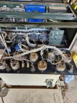
Don't see anything marked MT4 anywhere inside the control panel. Also, don't have a clue what it looks like.
 

Attachments

ErichLessing

New member
16
6
3
Location
Texas
I found MT4 on the schematic but I can't find it on the generator. Does anyone know where MT4 Battery Ammeter Shunt is physically located on the genset?

Don't see anything marked MT4 anywhere inside the control panel. Also, don't have a clue what it looks like.
How about this theory, the CR1 wire that gets smoking hot is the 162A20 wire. Per the schematic, 162A wire leads directly to S17 emergency stop switch. E-Stop suction only has 2 wires. If that switch was wired backwards, could that be the reason 162A gets hot enough to melt the solder and fry the CR1 Diode?
Can I cause more damage by switching the 2 wires on the E-Stop switch to see if that fixes the problem?
Thanks,
Erich
 

ErichLessing

New member
16
6
3
Location
Texas
Morning all,
I traced my cables from the batteries to the Slave Receptacle and the starter. The positive cable is set on the bottom of the Slave lug and then leads to the starter. The negative lead is on top of the Slave lug and then leads to frame ground lug. My multi meter showed 24VDC without a "negative" mark so I assume the polarity is correct. I will check MT4 and report.
How about this theory, the CR1 wire that gets smoking hot is the 162A20 wire. Per the schematic, 162A wire leads directly to S17 emergency stop switch. E-Stop suction only has 2 wires. If that switch was wired backwards, could that be the reason 162A gets hot enough to melt the solder and fry the CR1 Diode?
Can I cause more damage by switching the 2 wires on the E-Stop switch to see if that fixes the problem?
Thanks,
Erich
UPDATE: I swapped the 162A wire position on S17 E-Stop switch, Replaced the burnt CR1 Diode and re-soldered everything. I placed the genset S-1 in the Prime/Run position and checked the CR1 diode and 162A20 wire: NO HEAT. I tested the the fault panel: No Faults. Started the generator and had 2 faults: Overspeed and low voltage which shutdown the machine. I cleared the faults and reset the overspeed switch and restarted the machine. This time I held the S1 in the Start position for about 5-10 seconds. when I released the switch the low voltage fault light did NOT return but the Over-Speed fault came back. Trying to find info now in the TM's regarding a recurring Overspeed Fault. Partial WIN. Thanks to Guyfang for encouraging me to use the TM's and wiring schematic to troubleshoot these problems.
 
Top
AdBlock Detected

We get it, advertisements are annoying!

Sure, ad-blocking software does a great job at blocking ads, but it also blocks useful features of our website like our supporting vendors. Their ads help keep Steel Soldiers going. Please consider disabling your ad blockers for the site. Thanks!

I've Disabled AdBlock
No Thanks