• Steel Soldiers now has a few new forums, read more about it at: New Munitions Forums!

  • Microsoft MSN, Live, Hotmail, Outlook email users may not be receiving emails. We are working to resolve this issue. Please add support@steelsoldiers.com to your trusted contacts.

802a Burned Wiring at J7/P7

Toolslinger

Active member
83
165
33
Location
PA
Well, it became frigid again, so I guess I was heading back to the 802a...

The plan was to roll it outside the garage to see if it would run.

Topped up the batteries.
Hooked up the batteries.
S10 to Normal
S17 out
S1 to Prime/Run

And... Nothing.
No fuel pump ticking
Malfunction Indicator Panel had 2 lights on:
No Fuel​
Low Oil Pressure​
Pushed the Test/Reset. All lights came on. Release, still have the 2 fault lights.

Tried S1 to Start. Nothing as expected with fault lights on.

First thought was I had a bad crimp splice in those 2 circuits.

S1 back to Off
S17 In
Flipped the Battle short switch on
s17 Out
S1 to Prime/Run
Fuel pump came on.
Should have tried S1 to Start to see if it spun, but didn't think of it.

S1 Off
S17 In
S10 to Off.
Disconnect the batteries.

At that point I checked continuity through the 5 crimps that are associated with fuel level, fuel sender, and the LOP switch. They're all good.
Fuel tank is full, or right there. I had no fuel level, or sender issues prior to the burned wiring.

I had to walk away from it at that point as I was getting frustrated, and cold. I figured I can sit and try to make my way through the schematics sitting in the nice warm house, with a beer, and a much bigger monitor.
 

Guyfang

Moderator
Staff member
Moderator
17,011
24,836
113
Location
Burgkunstadt, Germany
Well, it became frigid again, so I guess I was heading back to the 802a...

The plan was to roll it outside the garage to see if it would run.

Topped up the batteries.
Hooked up the batteries.
S10 to Normal
S17 out
S1 to Prime/Run

And... Nothing.
No fuel pump ticking
Malfunction Indicator Panel had 2 lights on:
No Fuel (Here is the problem. The Low fuel system is telling the fault indicator to NOT let you start the set.)
Low Oil Pressure (Was the set running? No. So what should LOP tell you? Low Oil Pressure. )
Pushed the Test/Reset. All lights came on. Release, still have the 2 fault lights.

Tried S1 to Start. Nothing as expected with fault lights on. (Try this. Push the fault indicator reset and hold it up. Do not let go. Try and start the set with the S1. What happens? If it starts and runs, let go of the reset switch. What happens?) EDIT!!!!!

First thought was I had a bad crimp splice in those 2 circuits.

S1 back to Off
S17 In
Flipped the Battle short switch on
s17 Out
S1 to Prime/Run
Fuel pump came on.
Should have tried S1 to Start to see if it spun, but didn't think of it.

S1 Off
S17 In
S10 to Off.
Disconnect the batteries.

At that point I checked continuity through the 5 crimps that are associated with fuel level, fuel sender, and the LOP switch. They're all good.
Fuel tank is full, or right there. I had no fuel level, or sender issues prior to the burned wiring.

I had to walk away from it at that point as I was getting frustrated, and cold. I figured I can sit and try to make my way through the schematics sitting in the nice warm house, with a beer, and a much bigger monitor.
 
Last edited:

Guyfang

Moderator
Staff member
Moderator
17,011
24,836
113
Location
Burgkunstadt, Germany
If thats the problem. Could also be the Fault indicator. Or A9. Or a wiring problem.

Could be simply the FL1/FL2 is not adjusted right. Too shallow in the tank. The switch is turned so the bottom float is against the side of the tank. Something in the tank is interfering with the floats. The magnet in the float fell out. If I think long enough, I can come up with a few more.

Also forgot to write an edit to my post above.
 

Toolslinger

Active member
83
165
33
Location
PA
Guy - Tried per your suggestion.
S10 to Normal
S17 out
S1 to Prime/Run (no fuel pump ticking)
Push and Hold Test/Reset - All fault lights lit up
S1 to Start while holding Reset - No fuel pump, no crank.

I agree with the logic that it can't see OP when it isn't running. After reading the Initial Adjustments, Before Use and Self Test in the TM, it seems to indicate all fault lights should be out after releasing the Reset button (assuming there isn't actually a fault). Is that an error in the TM, or just badly worded? I'm working from 15 October 2009, which I thought was the most recent. Occasionally I overthink wording, so it's probably just my screwy brain...


Just as more info since I was there...
When I move S1 to either of the Run positions, K12 is triggered. No other relays move.

When I flipped the Battle Short, and moved to either Run, K16 is triggered, but nothing else, and of course, I get the fuel pump mentioned above.

I haven't looked in to either of those yet, but it's just more info.


Tomorrow I will try disconnecting the floats. Perhaps when I completely filled the tank the float mechanism crapped out by moving further than it wanted to.
If it's the fault panel, sadly the 400hz units seem to take a different part than the 60's, because I have the one from the 813a... But, one thing at a time...

Thanks for the thoughts so far. Amongst other things, I think I'm going to verify continuity on the few other splices I had to do. Should probably eliminate the simple possibilities first.
 

Toolslinger

Active member
83
165
33
Location
PA
Well, I wasn't going to go out there again tonight, but then I did...

Unhooked the fault indicator. Set the switches, and got the fuel pump ticking in the run positions. Clicked to Start, and it started to turn over. Didn't let it start. That was close enough for a closed up building. I will pull it outdoors tomorrow to see it it will fire off. Not planning to run it like that long. Will also try the fuel floats disconnected with the fault panel in first.

Happy to see a little progress. Many thanks!
 

CallMeColt

Well-known member
Supporting Vendor
1,075
1,582
113
Location
Wilson County, Texas
The fault indicator panel from the MEP 813A doesn't have GFCI. Not sure what else it is missing. Would guess it won't work at all and may be your issue?

The dual float switch can be adjusted but figured you'd have fiddled with that after re-wiring everything. Easiest way to do it is loosen the lock nut, rotate it a it each way to feel that it is in the sump and hit each side, move it to abut the middle. Then, lower until you hit the bottom of the tank, raise it 1/8in or so, then tighten lock nut without letting the float rotate itself.
 

Toolslinger

Active member
83
165
33
Location
PA
Also, didn't have to touch the float setup as the replacement harness was cut off before it got to the tank area, and I simply spliced it in without having to touch anything on the tank. I pulled the panel today, so I've got access to check now.
 

dav5

Active member
398
187
43
Location
Mono, Ontario
Guy - Tried per your suggestion.
S10 to Normal
S17 out
S1 to Prime/Run (no fuel pump ticking)
Push and Hold Test/Reset - All fault lights lit up
S1 to Start while holding Reset - No fuel pump, no crank.

I agree with the logic that it can't see OP when it isn't running. After reading the Initial Adjustments, Before Use and Self Test in the TM, it seems to indicate all fault lights should be out after releasing the Reset button (assuming there isn't actually a fault). Is that an error in the TM, or just badly worded? I'm working from 15 October 2009, which I thought was the most recent. Occasionally I overthink wording, so it's probably just my screwy brain...


Just as more info since I was there...
When I move S1 to either of the Run positions, K12 is triggered. No other relays move.

When I flipped the Battle Short, and moved to either Run, K16 is triggered, but nothing else, and of course, I get the fuel pump mentioned above.

I haven't looked in to either of those yet, but it's just more info.


Tomorrow I will try disconnecting the floats. Perhaps when I completely filled the tank the float mechanism crapped out by moving further than it wanted to.
If it's the fault panel, sadly the 400hz units seem to take a different part than the 60's, because I have the one from the 813a... But, one thing at a time...

Thanks for the thoughts so far. Amongst other things, I think I'm going to verify continuity on the few other splices I had to do. Should probably eliminate the simple possibilities first.
I bought a complete 400 Hz fault panel for my 803 and it works just fine. I do not use the GFCI so it may not function but everything else worked.
 
Last edited:

Guyfang

Moderator
Staff member
Moderator
17,011
24,836
113
Location
Burgkunstadt, Germany
The GFI is a separate part, attached to the Fault Indicator. And the wire harness between the two models will support the GFI, if you wanted to use it in a 400 hertz model control cube, grafted to a 60 hertz gen set.
 

Toolslinger

Active member
83
165
33
Location
PA
Got a later start on it today than desired despite starting my day at 2:30am...

It was behaving inconsistently. Or I suppose I should say more inconsistently.

Check batteries. One is almost flat again.

OK. Time for new batteries since it won't hold overnight. Ordered a couple 51R's. I'll pick them up in the AM along with another big battery for my backhoe. Turning in to a heavy battery season... This will make 5 in the last couple months. That's about 20% of the fleet here. Probably should do my car too as it's now 5 years old, and it's been sounding tired in this cold...
 

Toolslinger

Active member
83
165
33
Location
PA
After spending WAY too much time at WalMart getting my battery core charges refunded. ( I am not done with that miserable situation.)

Dropped the batteries in the unit. Lined up the switches with the fault panel unplugged, and moved to Run... Fuel pump was ticking, so that's good. I wanted to turn to Start just enough to hear the starter try, and then off, but it was so satisfied with the amount of headache it has caused that it started right up... Back to Stop.

Tried unplugging the floats. I had checked with a meter, and they seemed ok, but worth trying I guess. Plugged in the Fault Panel, and yea, still No Fuel, and No Oil Pressure.

So since Dav5 has a 400hz fault panel working for him, I looked closer at mine. Pulled the 813a's panel out, and plugged it in to the 802a's harness. Line up the switches, and turned to Run. No warning lights. Hit the Test/Reset, and they all came on. Figured I'm in business now.

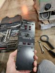
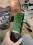
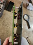
So I carefully opened the 813a's fault panel back case after unplugging from the 802a.
2025-01-04 12.14.12.jpg 2025-01-04 12.14.18.jpg 2025-01-04 12.16.56.jpg

4 Small nuts hold the back on. Then it's 4 more nuts holding the circuit board to the front panel, plus the nut holding the Reset switch to the front panel, and with a little wiggling, it comes right off.

Having now done that one, I was comfortable knowing I could do the 802a's without taking the front panel out of the generator. So out that came.

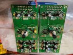
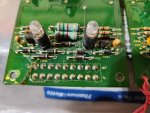
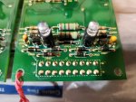
Quick visual inspection, and they're the same part based on comparing resistor values etc. And then, down at the bottom of the 802a's, I spotted the likely cause of failure... The board with the red twist tie is the 802a's. This picture came in upside down, so you're looking at the bottom of the boards.
2025-01-04 12.25.01.jpg

Let me zoom in a bit...
813a's:
2025-01-04 12.26.12.jpg

802a's. CR 45 is kinda roasted. I'll take it in to work, and take a closer look, but if that's the only issue, I should be able to repair that, and hang on to it as a spare.
2025-01-04 12.26.06.jpg

Put it all back together, and pulled the unit outside.
Started, and ran it for 10 or 15 minutes. No faults. Temp gauge was coming up a little, so I know that's at least wired right.

Checked the LOP switch, and that's working ok.

The DC amp gauge was swinging around drunk. So that's got an issue.

Shut down and back in the garage.

Pulled the Neg terminal.
Tried tapping on the DC Amps gauge, and it dances around toward the side you tap, so clearly there's a physical issue there. Tried tapping the 813a's , and it didn't budge, so I swapped that over. No idea if it works, but it can't be worse. I'll check that out next time I run it.

So it was on to final cleanup of wiring.

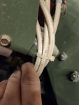
After reading another post with people mentioning abrasion of wires, I thought I'd check.
Yep. Paint abraded off where they were touching, and just a little fabric jacket fuzz.
2025-01-04 12.32.45.jpg

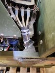
I don't have the aforementioned inner tubes... I do have lots of radiator hose, and nylon tube... So I ran those anywhere needed.
2025-01-04 14.48.56.jpg 2025-01-04 14.49.02.jpg

Once that was done, I spent time arguing with myself... I know I need to, and should do the PM work. On the other hand, I don't want to deal with spilled diesel in my uncles garage, and it's getting even colder. So I put the side panels, and fuel tank access panel back on. Lids will go on tomorrow, and PM is going to wait until Spring when I can do it either in my barn basement, or out front with tolerable weather. The stainless hardware came in, so at least that's getting taken care of. Can't leave it open due to potential rodent incursion.
I'm mostly hoping it sees no hours this winter. I think I'm not even going to put it out by the house. For a short outage the gas fired unit can handle things fine. If it gets crazy, there's pretty much no amount of snow that can stop the tractors from digging out, so I can always bring it over. Keeping it in the barn will keep it dry, and since it isn't convenient, I won't be tempted to run it.

Next task is to salvage any potential spare from the 813a carcass.
 

Toolslinger

Active member
83
165
33
Location
PA
The fault indicators have different part numbers for a reason.
I can't argue that. The -24P indicates the fault panel as a complete assembly, rather than the internal board I just swapped. It might be as simple a difference as the cutout for the ground fault portion on the 802's setup. As I understand it, the Fault Indicator only tells you what it is being told by the various safety switches/sensors, and then shuts the units down based on that. I don't believe it ever sees the generated voltage, so I can't imagine why they'd make a different board since the fault logic doesn't change. It would take someone far more comfortable looking at the schematics to determine if there's a difference in the signals that the 60hz, and 400hz units produce to feed it.
 

Toolslinger

Active member
83
165
33
Location
PA
The circuit card should have a part number on it.
You are right. I took a quick look when I was swapping, but didn't see it. Cold, not great light, etc. There are a couple identifiers on the back of the card, so I can check by just popping off the back cover tomorrow. I'll stick my phone in there, because it's eye is way better than mine at this point.
 
Top
AdBlock Detected

We get it, advertisements are annoying!

Sure, ad-blocking software does a great job at blocking ads, but it also blocks useful features of our website like our supporting vendors. Their ads help keep Steel Soldiers going. Please consider disabling your ad blockers for the site. Thanks!

I've Disabled AdBlock
No Thanks