• Steel Soldiers now has a few new forums, read more about it at: New Munitions Forums!

  • Microsoft MSN, Live, Hotmail, Outlook email users may not be receiving emails. We are working to resolve this issue. Please add support@steelsoldiers.com to your trusted contacts.

Help with mystery wire identification

Zeus51

Active member
154
47
28
Location
Birmingham, AL
The blower motor grounds through the box it is mounted to. Most times the members here will tell you to run a second ground from the blower motor to another ground point (negative bus bar). That is what I did.

the horn is self grounding by the mounting bolt, just remove the horn and clean the bolt, horn where it bolts on and the point on the radiator support where it bolts on.

can you do a continuity check through the left side marker? All lights and power off, check continuity through both wires with the bulb in place.

I am still pondering all the light issues. I will get back to you on those.
I’m not sure how to check the continuity with the bulb in place. See pic. I can’t get my meter leads to a place on the wires. Would you cut the wires again and then do it? I did check continuity with bulb out and placed one lead on the ground piece and the other on piece that pinches the bulb. Does that work or just test the actual socket? i was thinking the socket. It checked out fine and the bulb works too
 

Zeus51

Active member
154
47
28
Location
Birmingham, AL
All of the rear lights share BRN-9A for power.

There may be one weak point in all of this, the fuse panel itself with the bulkhead connector. Have you done anything to take it all apart and clean all the contacts and tighten up the fuse connectors? I have completely gone through the whole thing on mine and found several fuse holder contacts that had to be adjusted.
I have not taken the fuse holder off but I did ensure the connectors were all clean. I’ll pull the fuse panel start cleaning. That’s a good idea
 

Zeus51

Active member
154
47
28
Location
Birmingham, AL
I have been reviewing the wiring diagrams. The voltmeter light is strange, but as it is supposed to be connected to the light for the heater control also, please see if it is blinking as well. Power for that circuit comes from the light switch to the bottom left fuse then provides power for all of the backlighting in the cluster.

Front and rear turn signals have separate circuits. They do not cross.

All four front turn signals/marker bulbs all share the Brown -9A that brings power from the headlight switch.
The front left turn/markers share LT Blue-14A that goes to the left turn indicator in the cluster to the turn signal switch back out on Brown -27 to the flasher at the top left of the fuse box

Thee right front turn/markers do the same thing but use DK Blu-15A
This is excellent info that I can use to trace voltage at certain points.

I’ve pulled the headlight harness out of the loom all the way back to the wiper reservoir and didn’t find any breaks or something that looked like issues. I’m starting to think my issue either at the fuse box or under the dash somewhere like you suggested. So I’ll start tracing the first day I get
 

deank

Well-known member
Steel Soldiers Supporter
313
490
63
Location
Florida
Just looking at the wiring again. If you take the bulb out of the left front turn/marker you can check for continuity on the bulkhead connector on the LT BLU -14A and the BRN-9A to test the sidemarker circuit. Disconnect the bulkhead connector first.
 

deank

Well-known member
Steel Soldiers Supporter
313
490
63
Location
Florida
Just a thought, you can also check the continuity without the bulb. Just check from each side of the bulb socket to the corresponding wire at the bulkhead connector with the bulkhead connector disconnected. Front bulb removed also.
How is the snow?
 

Zeus51

Active member
154
47
28
Location
Birmingham, AL
Just looking at the wiring again. If you take the bulb out of the left front turn/marker you can check for continuity on the bulkhead connector on the LT BLU -14A and the BRN-9A to test the sidemarker circuit. Disconnect the bulkhead connector first.
I did this. And while I was there I checked continuity from bulkhead connector to the light connections for lt blue, brown, and even dark blue for right side. All wires checked out. The blinking dash light that blink in sequence with the blinker got me thinking, I don’t think this is how it was originally wired. See pic for reference.

Are you voltmeter wires wired this way to a small dash bulb socket?in the second pic, the bulb in the top right of the pic is the one that blink in sequence with blinkers.

Also, what are you cleaning the bulkhead connection with? Did you pull each spade out of the connector to clean the spades?
 

Attachments

deank

Well-known member
Steel Soldiers Supporter
313
490
63
Location
Florida
For the bulkhead connector I use an electrical connector spray cleaner available at any parts store. Tall red can, cannot remember the name.

in pic 2, if I am looking at it correctly, the wires in your hand are for the light for the volt meter. It is sharing a ground with the voltmeter connector.

The other bulb should be for the heater controls. It should NOT flash with the turn signal. It should connect to the same positive and negative as the light for the voltmeter. They are on the same circuit.

If you can backtrace the wires for the light that is flashing we might find the issue.

Based on all the wires you checked for the front, all the front lights should be working. I still do not understand the left front side marker not working. Just for grins and giggles, swap the side marker bulbs. But, fixing the heater light might find that problem. Who knows…. We will figure it out.
 

Zeus51

Active member
154
47
28
Location
Birmingham, AL
For the bulkhead connector I use an electrical connector spray cleaner available at any parts store. Tall red can, cannot remember the name.

in pic 2, if I am looking at it correctly, the wires in your hand are for the light for the volt meter. It is sharing a ground with the voltmeter connector.

The other bulb should be for the heater controls. It should NOT flash with the turn signal. It should connect to the same positive and negative as the light for the voltmeter. They are on the same circuit.

If you can backtrace the wires for the light that is flashing we might find the issue.

Based on all the wires you checked for the front, all the front lights should be working. I still do not understand the left front side marker not working. Just for grins and giggles, swap the side marker bulbs. But, fixing the heater light might find that problem. Who knows…. We will figure it out.
Does that bulb socket usually share a ground with the voltmeter? I’d like to get it back to factory. So i am thinking about taking down that connector and reattaching the normal wiring in the usual manner.

Regarding the heater control bulb socket that blinks, The harness that goes to it seems to still be intact and unaltered. You’re saying, your pull all that old factory tape off and investigate? happy to do so, but I would assume if someone did something to it, then it would have new tape or look altered
 
Last edited:

deank

Well-known member
Steel Soldiers Supporter
313
490
63
Location
Florida
I researched the diagrams again. The light for the voltmeter should NOT share a ground with the voltmeter, that wire goes through a relay to get to ground.

The voltmeter light and the heater control light are on a circuit together. The ground will terminate at the firewall with all the other grounds at the spider. The positive wire is from the fusebox, fuse 13, 5 amp indtrument lights. The wire is gray. With power OFF test for continuity of each bulb socket wire to ground and to that fuse.
If I am right about the voltmeter light, it may have continuity to the fuse but not ground because the relay will be open.

I think the heater bulb socket will be grounded to the spider but is getting power through a different wire, it will really need to be traced.
1738028877179.png
 

Zeus51

Active member
154
47
28
Location
Birmingham, AL
I researched the diagrams again. The light for the voltmeter should NOT share a ground with the voltmeter, that wire goes through a relay to get to ground.

The voltmeter light and the heater control light are on a circuit together. The ground will terminate at the firewall with all the other grounds at the spider. The positive wire is from the fusebox, fuse 13, 5 amp indtrument lights. The wire is gray. With power OFF test for continuity of each bulb socket wire to ground and to that fuse.
If I am right about the voltmeter light, it may have continuity to the fuse but not ground because the relay will be open.

I think the heater bulb socket will be grounded to the spider but is getting power through a different wire, it will really need to be traced.
View attachment 939859
I’ll test continuituy as soon as i can for the grey wire. Quick wiring diagram question. The wiring diagram says .8 Wht 950 along with an orange wire supplies voltage to the voltmeter. But mine has a black wire with white stripe. Do you think that’s the correct wire? Do you know what yours has?

Also, according to the diagram, it looks like the two bulb sockets share a splice for ground. But that is not how mine is wired. It’s starting to definitely look like I need to take down the harness tape under the dash and trace wires.

Sorry for asking so many specific questions about yours, but I am trying to figure out what is truly stock so I can return it to its intended use.
 

Attachments

deank

Well-known member
Steel Soldiers Supporter
313
490
63
Location
Florida
The next time I go out to mine I will poke my head under the dash and get some pictures of mine.
 

deank

Well-known member
Steel Soldiers Supporter
313
490
63
Location
Florida
I have been rereading the posts. When a turn signal is turned on the front bulb and side marker are supposed to blink alternately.
 

Zeus51

Active member
154
47
28
Location
Birmingham, AL
I have been rereading the posts. When a turn signal is turned on the front bulb and side marker are supposed to blink alternately.
Really? I guess I never noticed that on the other ones. But it is good to know that the front right is actually working correctly with lights on. I’ll be tearing down the dash harness to trace the volt meter wiring because the two wires currently wired to it are Black with white strip and orange wires. And diagrams have white wire and orange wire going to it. I am really hoping I trace the black/white stripe wire to the relay where its suppose to go
 

Zeus51

Active member
154
47
28
Location
Birmingham, AL
ok. I took down the harness and traced some wires. The grey bulb socket wires do seem to follow the wiring diagram. My funny shared ground to volt meter is a different story. When the diagrams say white wire leaves the VM relay and goes to the volt meter, they meant black wire with white strip. So I took the bad wiring down and made sure the bulbs shared the ground same as is in the diagram. But it got me thinking. Is the wrong volt meter relay and gen 2 relay installed? See pic, this is what I’m currently using. Should I have 322-204-151? I couldnt find any and I found these that had the same current switch diagram.
 

Attachments

Zeus51

Active member
154
47
28
Location
Birmingham, AL
I have been rereading the posts. When a turn signal is turned on the front bulb and side marker are supposed to blink alternately.
Latest update. I have:

Changed switches like: turn signal switch in the column, brake light indicator, headlight switch,

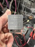
Changed relays behind the cluster taped to the top of the dash, the Vm relay, gen 2 relay, new flasher relay, new turn signal relay

All new fuses. And fuse box in cab and on the bulkhead was cleaned.

Cleaned grounds at: left and right of radiator, the radiator to frame, spider in the dash, L and R brake light housing, the trailer connector ground in rear crossmember, new busbar to engine cable, changed the engine to cab strap,

Checked continuity with batteries disconnected of: Lt blue turn signal to bulkhead connection, dark blue turn signal to bulkhead, Lt blue turn signal to wire bundle that plugs into the instrument cluster, I even checked Lt blue turn signal to the actual turn signal switch. ALL check out

I fixed the shared ground at the vm and vm light. After tracing the wires under the dash.


Now, this is where the service light situation is at the moment.

Service light on, lights off with left turn signal engaged: results in left gauge cluster light, lights behind Speedo and fuel, vm light, heater control light,
Both rear tail lights, both front indicators and the right side marker all flash at pace. Nothing from left side marker.

Service light on, lights off with right turn signal engaged: light in cluster for right turn signal, front turn signal and side marker blinks at normal pace no right rear blinker.

Service light on, lights on and no turn signals engaged: all four corners turn on except front left side marker, as well as left blinker in cluster is on steady. VM and heater light on steady as well as cluster

Service light on, lights on and right turn signals engaged: front indicator and side marker blink, rears stay on but don’t blink, right turn light in cluster blinks normal. The vm and heater control light do not blink. But the left signal in cluster is still on steady

Service light on, lights on and left turn signals engaged: all lights on. Right turn signal and right side marker blink at pace, left turn indicator is on steady, left side marker is off.

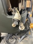
Under all circumstances the front left side indicator stays off. I have changed this bulb socket twice bc I thought I crossed my wires but I’ve tried it both ways and it’s currently wired so I produced a positive voltage on my meter. So I feel good that positive is to positive and ground is to ground.

Hazard flashers ON with headlights off: rear and fronts blink as they should. Neither side marker blink. Even the lights in the cluster, both blinkers, vm light and heater controls blink with the hazard lights.

Hazard flashers ON with headlights ON: ZERO blinking all around


so basically, I’m running out of ideas for Troubleshooting.
 

deank

Well-known member
Steel Soldiers Supporter
313
490
63
Location
Florida
Good evening,


I am attaching a picture of a checklist of the lights so we are both understanding the same indications. based on the switch settings just put an "X" in the correct column and save as the same filename with CHG1 at the end of the file name. That way we can change the CHG number to keep up with things as we go.

Also, before we go further let's take a look at the rear lights. If you disconnect the harness for all of the rear lights at the left rear of the frame we can test each circuit with a voltmeter to ground. there are only 4 wires to deal with 2 stop/tail/turn and 2 for backup. I want to know what is crossed for the right side to light up when the left turn signal is on.

Then we can figure out why backlight bulbs are flashing when the left turn signal is on.

Lastly, we can figure out the left marker light.

EDIT: I forgot a switch setting. Should be good to go now.

light test sheet.png
 
Last edited:

Zeus51

Active member
154
47
28
Location
Birmingham, AL
Good evening,


I am attaching a picture of a checklist of the lights so we are both understanding the same indications. based on the switch settings just put an "X" in the correct column and save as the same filename with CHG1 at the end of the file name. That way we can change the CHG number to keep up with things as we go.

Also, before we go further let's take a look at the rear lights. If you disconnect the harness for all of the rear lights at the left rear of the frame we can test each circuit with a voltmeter to ground. there are only 4 wires to deal with 2 stop/tail/turn and 2 for backup. I want to know what is crossed for the right side to light up when the left turn signal is on.

Then we can figure out why backlight bulbs are flashing when the left turn signal is on.

Lastly, we can figure out the left marker light.

EDIT: I forgot a switch setting. Should be good to go now.

View attachment 940100
The chart will be the next thing I do when I get a chance. In the mean time, any chance you could help me identify which rear bulb is intended for which purpose? I’ve tried to look at diagrams and manuals to figure out which is suppose to be rear backup light vs brake light vs service light but can’t find it.

I also checked continuity to all rear connections like you recommended. The rear right dark green wire was severed but is now repaired and functions. All other wires check out for continuity.
 

Attachments

RattleSnack

New member
9
20
3
Location
Ford City, PA
The 194 (or 169) bulb is your side marker. Wires are brown & black.

The 1156 bulb (Single filament) is your reverse light. Wires are light green & black.

The 1157 bulb (Dual filament) is your Stop, Tail, & Turn signal light. Wires are Brown, Black & Yellow.

2025-02-04 11_07_46-CUCV REAR SERVICE LIGHTING CIRCUITS color.jpg
 

Zeus51

Active member
154
47
28
Location
Birmingham, AL
The 194 (or 169) bulb is your side marker. Wires are brown & black.

The 1156 bulb (Single filament) is your reverse light. Wires are light green & black.

The 1157 bulb (Dual filament) is your Stop, Tail, & Turn signal light. Wires are Brown, Black & Yellow.

View attachment 940201
Thanks dude. Hey, teach me something, did you derive that info from the pic you posted? I’m asking bc on that diagram, the other tail light has the wording in the far right “tail stop die side mkr & B/u Lt” in the same descending order. So I didn’t think the wording was associated with the bulbs it was beside.
 

RattleSnack

New member
9
20
3
Location
Ford City, PA
Thanks dude. Hey, teach me something, did you derive that info from the pic you posted? I’m asking bc on that diagram, the other tail light has the wording in the far right “tail stop die side mkr & B/u Lt” in the same descending order. So I didn’t think the wording was associated with the bulbs it was beside.
The wording is just a description of the left tail light assembly. TAIL, STOP, DIRectional SIDE MarKeR, & BackUp, Left. They don't correspond to the bulbs as shown. But if they were, the correct description from the top down would be:

BackUp Light
Tail-Stop (& Turn) Light
Side Marker Light
2025-02-04 11_07_46-CUCV REAR SERVICE LIGHTING CIRCUITS color.jpg

Plus, I've been driving and working on squarebodys for oh...almost 30+ years now. Some things just get burned into my memory. Now if I can only remember the wife's birthday.... :unsure:
 
Top
AdBlock Detected

We get it, advertisements are annoying!

Sure, ad-blocking software does a great job at blocking ads, but it also blocks useful features of our website like our supporting vendors. Their ads help keep Steel Soldiers going. Please consider disabling your ad blockers for the site. Thanks!

I've Disabled AdBlock
No Thanks