• Steel Soldiers now has a few new forums, read more about it at: New Munitions Forums!

  • Microsoft MSN, Live, Hotmail, Outlook email users may not be receiving emails. We are working to resolve this issue. Please add support@steelsoldiers.com to your trusted contacts.

002A Aux Fuel Setup Suggestions

Guyfang

Moderator
Staff member
Moderator
16,229
23,001
113
Location
Burgkunstadt, Germany
I'm looking at the schematic you posted. I also pulled it down from both the 003 and the 002 -34 manuals. (yes, I'm learning allot!). Looking at the circuit from the Fuel Tank Float Switch (S3) going right I have a few questions:
the ">>" or "<<" labeled as J4-B or J5-B, are connectors such as the "canon plug" Guyfang noted, and the "P63A16" is the wiring harness part number?

Also, if I follow the circuit just before CR3, I see TB4-11. I'm having a hard time figuring out what that is. I am thinking it is the Fuel Pump Capacitor. But with that, I'm also lost to where/what the Diode (CR3) is.

Thanks to all.
J4 is the plug. J4-B is the plug number and pin letter in that plug. If you look real close at them, you will see tiny little letters next to the pins.

P63A16 is a Wire number. Each wire has its own number. Ignore the last two numbers. That tells you the gage of the wire. So you only really need P63A.

TB means Terminal Board. It's a long, (or short) strip of terminals, where you hook up wires. If you open the control panel door and look in, you should see TB4. TB4-11 is the terminal board and the 11 means the 11th connection. There will be numbers printed above or below the TB, to help you find it. Normally read from left to right, or from top to bottom.

If i remember right, the CR3 is mounted directly on the TB. I am using a phone to do this and can't look at my TM's. The CR3 is needed to keep the K4 from being energized from back feeding of voltage.
 
Last edited:

n5yzv

Member
84
0
6
Location
Boerne, TX
That helps immensely! I plan to do the testing on the solenoid side of the circuit today or tomorrow. I also need to do another mini-load test. I was pulling 21a from one leg of the 240 and 11a from the other. I measured 113v on the 21a leg, 120v on the 11a leg. I am moving my short circuit breaker box wiring (5 ft - 10 gauge) to 2 gauge aluminum. This way, I know I don't have too light of wire getting to the breaker panel and will test voltages at the Gen as well. I got a bad feeling I have a underperforming voltage regulator.
 

Guyfang

Moderator
Staff member
Moderator
16,229
23,001
113
Location
Burgkunstadt, Germany
Since your Handle is n5yzv, you got to be a Ham. So this stuff should be easy for you.

When you did your measurements, did you use a multimeter, or the gages on the panel?
 

n5yzv

Member
84
0
6
Location
Boerne, TX
Yeah, I got my Tech ticket around 1989. I dabble here and there. I need to get my HF gear on the air. Work wise, I do "all kinds of stuff IT". So I love a good challenge. I was using a "decent" digital multimeter. I don't trust the gauges. In fact, I'm working on a good ready to pony up and buy an oscilloscope. It may be helpful if I have to rebuild the voltage regulator, but really, the components are not very exotic, so most can be tested with a decent meter. The scope would be very handy for evaluating the quality of the power output however. That is kinda impossible to do otherwise.
 

Guyfang

Moderator
Staff member
Moderator
16,229
23,001
113
Location
Burgkunstadt, Germany
The gages are to be taken with a grain of salt. And at the end of the day, they are close enough for government work. When I was in ADA, we powered all kinds of radars, vans, launchers and what have you. 416 volt, 400 hertz. Precise Power gen sets. But said with a smirk. We went by the meters, and very rarely checked line out.

Yeah, an O-Scope is what you need to do that kind of repair. Volt reg's are costly, to buy, simple to repair. Its 1950-60's technic. But good tools are a must.
 

n5yzv

Member
84
0
6
Location
Boerne, TX
Yeah, this is my thinking. There is probably $30 worth of Resistors, Diodes and Cap's on that board. I'm seeing prices $200+ for a "used, but tested" board. I can have a nice scope setup for about $400, and I can SEE the sine wave of the power the gen produces. Not to mention, I am constantly running across power issues at customer locations. My "gut" tells me it's power and I ask for the customer to trust me. They typically do. Sure would be nice to prove it.
 

n5yzv

Member
84
0
6
Location
Boerne, TX
I think I'll take a good pic of the board, order a few of the resistors, diodes and caps, etc..., get the new ones on the bench. Then, learn how to test the new items. This way, I have a good benchmark of what I should see on the actual voltage regulator. Most of this should be tested by my digital multimeter. Has the settings for testing diodes, caps, etc...
 

Guyfang

Moderator
Staff member
Moderator
16,229
23,001
113
Location
Burgkunstadt, Germany
Take a good gander at the -24P. The parts are 1950-60's tech. You can probably find something better. It would be nice if someone collected old board, diagnosed the part failure and then "improved" on that part. Bad board could be fixed and re issued/sold. Hint, hint.
 

n5yzv

Member
84
0
6
Location
Boerne, TX
I would bet it would be pretty cheap to build a new board, new components giving new life to a gen. I'll pull up the -24P and check it out. When I grab some lunch, I'll take a few pics of my existing one. I have a funny feeling mine is not running as good as it could be. When I throw a load on it, the voltage needle drops quite a bit, where as I see some video's online that barely dip. Sure, maybe my meter on the unit is goofy, but still, a sign.
 

n5yzv

Member
84
0
6
Location
Boerne, TX
I took a few pics. After seeing the components, I'm very tempted to replace everything. I'm picking up a LCR meter to test the cap's while they are still mounted, but I see a few that look corroded. I can't imagine that helps voltage stability. I also did another test. 240, single phase. L1 - (120v) 9.4 amps, L3 - (114v)12.5 amps, N(L0) - 7.0 Amps Umm....I thought the L0 should measure the difference between L1 & L3?? I also see the voltage needle dip quite a bit when I flipped the breaker on (fan with a 1-2 hp motor, 120v reading) and a 1500w elec smoker on the other leg (120v reading). I also checked the voltage at the lugs, and it was the same. I was checking the amp at the wire coming off of the lugs.
So, does this sound like voltage regulator issues?
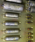
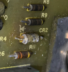
Screen Shot 2017-11-08 at 2.04.09 PM.pngScreen Shot 2017-11-08 at 2.05.11 PM.png
 

Guyfang

Moderator
Staff member
Moderator
16,229
23,001
113
Location
Burgkunstadt, Germany
I can not tell you how many such cards I have looked at during my years of repairing gen sets. Clasic. Clasic damage. I would not rule out other deteration of components in the Static Excitor. But would not bet on it. This was probably the biggest weak point of the 004 and 005 family of gen sets. If you had a precise set, then we could really talk about problems! In the beginning we had a electro-hydraulic system for engine control. It worked. But that's the only positive thing I can say about it. Then came the fully electronic governing system. Much better, but still not real good. Be glad you don't have the precise model!

The dip in voltage could also be crappy contacts in the K1. And the K1 is world famous for getting wet inside the housing. Often, the K1 output contacts were damaged when people got in a hurry to shut off the set, under load. Simply flip the S1 down, and walk away. Not good!
 

Zed254

Well-known member
866
466
63
Location
S. Hampton Roads, VA
I use a 240vt electric stove when testing my machines and noticed a difference in amps being pulled on each leg. I was thinking they should be equal until I remembered the 120volt control circuit and oven light. That current was returning on the Neutral leg. I checked mine by removing the 120vt light and noticed a reduction in the N leg's amps. When I added the Neutral amps to the leg that was 'missing' amps it totaled very close to being equal to the leg with the higher amp reading.

I'm wondering if your 9.4 amp vs 12.5 amp vs 7.0 amp difference could be caused by the difference in the various 120vt components you are using to consume the generator's power. They don't add up as nicely as mine did, but I was only using a single 240 volt stove.
 

n5yzv

Member
84
0
6
Location
Boerne, TX
Yeah, at the moment I have only 120v items. I am considering picking up a shop heater that low is 5000 watts, high is 7500 watts. Kinda seems like a waste buying a large heater in Texas though.

I'll take a look at K1's contacts. I'm not real familiar with it, but I am guessing it is some sort of relay. Regarding the "Static Excitor". Umm....is that the voltage regulator side that charges the battery? If so, that is not putting out voltage on mine. I have a 7amp 24v battery charger (by noco) that is handling that for now. As I make my way through the entire system, I figured I would get around to it.

I figure with a good cap tester and my digital multi meter, I'll just start poking around and testing components, starting with the VR that in the control head.
 

Guyfang

Moderator
Staff member
Moderator
16,229
23,001
113
Location
Burgkunstadt, Germany
K1 is your output contactor. It's mounted on the relay table.

The static Excitor is the box you got the volt reg out of. Also mounted on the relay table.

the battery charging alternator has a fuse mounted on it, so check it and see if it's there, (about the most stolen item this side of Pluto!) and or if it's good. 30 amp glass fuse. Plastic cover, ( second most stolen item) it just screws in.
 

n5yzv

Member
84
0
6
Location
Boerne, TX
And: Thanks Again. In blind faith, I ordered a replacement K1. I figure, why not. I also have on order the 7.5a dc breaker (mine is goofy), fuel cap, oil pressure switch (for some reason my leads to it are shorted out, assuming it is bad). With this all swapped, and I go through the voltage regulator board I'll be getting much closer. I'll check the fuse for the "alternator" that charges the batteries/provides dc in a bit. Oh, and I need to pull that solenoid out and show it some love. At some point, I need to get the ASK back on. The insulation is falling apart. What would you recommend replacing it with?
You know, this is kinda like rebuilding an old car. Kinda fun. At times. Heh.
 

Chainbreaker

Well-known member
1,751
1,855
113
Location
Oregon
I would bet it would be pretty cheap to build a new board, new components giving new life to a gen. ... I have a funny feeling mine is not running as good as it could be. When I throw a load on it, the voltage needle drops quite a bit, where as I see some video's online that barely dip.
Just as an option, there is a SS member "TripleJim" who builds a really nice replacement VR board. Uses modern day components and the output transistor is much better heat sinked. Several members have one, including myself, and really like it. His service is excellent and he offers a 2 year warranty on it.

Here is a link to it: http://lakeserv.net/mep/ac_regulator/index.html
 

n5yzv

Member
84
0
6
Location
Boerne, TX
Dam, that seems like the way to go. The age of the components by itself suggests they are not working optimally. Add to the fact of sourcing the parts, doing the overhaul and such. I also see they have the DC Voltage Regulator too. I may just replace both to get "more up to date" on these components. The rest of the Generator seems much more simple in design. Oh, something I noticed yesterday. On the back of my volt meter, there was a coil between the connections that broke. Do I need to replace it and if so with what?
 

Chainbreaker

Well-known member
1,751
1,855
113
Location
Oregon
...Oh, something I noticed yesterday. On the back of my volt meter, there was a coil between the connections that broke. Do I need to replace it and if so with what?
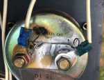
There should not be any components on the back of any of the "OEM" Panel gauges that I am aware of. Here are some shots of the inside of my '91 panel gauges as a reference:

WP_20171109_001.jpg WP_20171109_002.jpg WP_20171109_003.jpg
 

Chainbreaker

Well-known member
1,751
1,855
113
Location
Oregon
Hmmm, not good...not sure why anyone would have put that there. Also, not only did it break it appears to have shorted to the gauge's case.
 
Top
AdBlock Detected

We get it, advertisements are annoying!

Sure, ad-blocking software does a great job at blocking ads, but it also blocks useful features of our website like our supporting vendors. Their ads help keep Steel Soldiers going. Please consider disabling your ad blockers for the site. Thanks!

I've Disabled AdBlock
No Thanks