• Steel Soldiers now has a few new forums, read more about it at: New Munitions Forums!

  • Microsoft MSN, Live, Hotmail, Outlook email users may not be receiving emails. We are working to resolve this issue. Please add support@steelsoldiers.com to your trusted contacts.

2009-1093A1R LVAD Electrical Issues

1Pineapple

Member
19
33
13
Location
New York
1. Battery disconnect rely bypassed both 24volt and 12 volt
2. K11 at PDP no power
3. CB 70 Tripps out lights won't stay on.
4. Seems like someone back feed 24 volts into system.
5. Ignition relays clicks but start switch does not turn truck off
6. Truck only turns off with battery disconnect
 

Attachments

GeneralDisorder

Well-known member
Steel Soldiers Supporter
2,038
5,225
113
Location
Portland, OR
Ok I've been talking to 1pineapple over the phone on this issue.

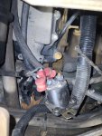
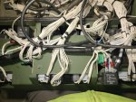
So the truck has three major issues at the moment - the ignition switch does trigger both ignition relays and they do click. But there's still 24v on 87 and 30 on the 24v relay so the truck doesn't shut down. Given that someone bypassed the 24v side of the remote disconnect relay (but not the 12v so there was no 12v power to the 12v ignition relay) I'm guessing that someone also stuck a jumper somewhere and back-fed the 24v ignition switched circuit. The relay by the starter is dangling from it's wires...... any guesses where someone may have jumped 24v into the ignition switched circuit? Nothing appears to be messed with in the PDP area.

The one thing I didn't consider is possible welded contacts in the 24v ignition relay but that seems unlikely since it clicks and the 12v relay works fine. I suppose we should check for that though I haven't seen that before - anyone seen that happen?

The other issue - after we jumped out the 12v side of the remote disconnect relay the MMDC came online but the lighting circuits seem to have a short or high draw somewhere as the gauge back lights and marker lights flash on and off and eventually trip CB70. It will continually trip if you try to reset it.

Finally - there is no 24v getting to the E terminal of the VR. K11 doesn't click when you pull and reinstall it while running and he swapped it with another one so the assumption is that there is no 24v getting to the NC contact (87a) so probably no supply voltage to the relay.
 
Last edited:

Ronmar

Well-known member
3,848
7,480
113
Location
Port angeles wa
Ok, lets start with the last one. K11 should NOT go click when when you pull it while running as it should be de-energized. It should go click when you turn on the ignition switch. 24v ign power flows thru CB77, and thru the neutral relay K26 energized contacts(30-87) to reach K11s coil. The TCM powers K26 when in neutral And K26 in turn powers K11 when in neutral.

The other side of K11s coil goes to the de-energized(30-87A) contacts of K40. K40 is controlled by the annunciator module and it energizes K40 above 350 RPM. This removes the ground to K11 which de-energizes it, which should shift power from CB77 to the alternator thru its 30-87A contacts. So with 24v ign applied, K26 and K11 energize.

in fact K11 MUST energize, as it is this same power from CB77 used for the alternator when de-energized, that powers the start switches via its 30-87 contacts when it is energized.

So when ign is turned on, the trans controller powers up in neutral energizing K26. K26 powers K11 and since the engine is not running, K40 provide a path to ground energizing K11. Once you start the annunciator powers K40, de-energizing K11 which disables the starter and brings the alternator online. Since the annunciator or K40 could fail, leaving the alternator offline, they backed things up by powering K11 thru the neutral start relay, so shifting out of neutral de-energizes K11 which then brings the alt online allowing you to complete the mission.

Either K11 is operating, or it has been bypassed to enable the starter buttons… if you can pull K11 out of circuit and it still starts, then the start circuit has been bypassed…


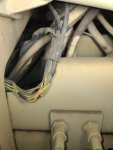
because of the use of the modular PDM boxes on the R, the most logical place to bypass the 24V ignition relay is at the relay itself. If the contacts are not fused, I suspect you will find both wires on one terminal, or otherwise connected together when the frame is lifted out of the dash To get to the relays. This is an A1 pic, but the R has the ign relays in the same place and they replaced the circuit board with modular PDM boxes.

9BF71EC3-552B-444F-AEEC-B66EF23E5719.jpeg
 

Ronmar

Well-known member
3,848
7,480
113
Location
Port angeles wa
CB70 is the main power feed to the main light switch. The main light switch in turn feeds several other circuit breaker circuits CB 54, 65, 73 and 74. As well as various other lights and circuits. It could be a combination of bad circuits or bulbs(does it have LEDs?) that are drawing too much current for the main CB70 to handle. I would probably start by pulling CB 54, 65, 73 and 74 and see if that lowers the current enough to keep CB70 engaged… but this will probably require disconnecting and measuring each circuit current draw compared against what the loads it powers should be drawing…

A likely spot for issues since you mentioned marker lights are where the door marker light wires pass from body to door. Easy to get damaged/chaffed and short to ground here… or you could have light sockets/LED circuits compromised by moisture/corrosion drawing excessive current…
 

GeneralDisorder

Well-known member
Steel Soldiers Supporter
2,038
5,225
113
Location
Portland, OR
Right - I knew the K11 NC contacts powered the E terminal and so I had him pull it to see if it was in fact still being powered and thus not sending the excite signal to the VR. The idea being if it clicks when you insert it (while running) then obviously the issue is that K11 isn't de-engergized and thus no power to E. Since it didn't click that would seem to indicate the power isn't getting to pin 30 on K11 and thus not flowing to 87A and on to the E terminal.

So sounds like someone may have bypassed the starting circuit and perhaps CB77 is not getting power or is tripped or bad.......

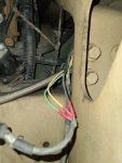
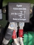
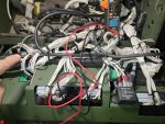
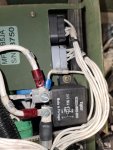
I'll post up a picture of his 24v ignition relay connections. My truck isn't available to compare at the moment and I don't know the wire numbers either so not sure if the three wires that are connected to it are oriented correctly. He did say it doesn't look like it's been touched though......

IMG_20230102_124120.jpg
 

Ronmar

Well-known member
3,848
7,480
113
Location
Port angeles wa
The 24v ign relay K1 should have 4 terminals on its pin 30. TL156, 512, 665 and 709. That is the 24v battery side.

K1 pin 87 should have 3 terminals. TL157, 667 and 711. This is the 24v ign side…
 

GeneralDisorder

Well-known member
Steel Soldiers Supporter
2,038
5,225
113
Location
Portland, OR
CB70 is the main power feed to the main light switch. The main light switch in turn feeds several other circuit breaker circuits CB 54, 65, 73 and 74. As well as various other lights and circuits. It could be a combination of bad circuits or bulbs(does it have LEDs?) that are drawing too much current for the main CB70 to handle. I would probably start by pulling CB 54, 65, 73 and 74 and see if that lowers the current enough to keep CB70 engaged… but this will probably require disconnecting and measuring each circuit current draw compared against what the loads it powers should be drawing…

A likely spot for issues since you mentioned marker lights are where the door marker light wires pass from body to door. Easy to get damaged/chaffed and short to ground here… or you could have light sockets/LED circuits compromised by moisture/corrosion drawing excessive current…
This truck should be 100% LED like mine. Doesn't have door markers (A1R's don't have them). But that's a good call to pull out the other CB's and see if we can narrow down the circuit that's the problem.
 

1Pineapple

Member
19
33
13
Location
New York
Wow you guys are amazing. I am on the road now but when I get home I will check into some of these things. My PDP looks nothing like yours Ronmar. Yours looks new even though mine is a 2009.
 

Ronmar

Well-known member
3,848
7,480
113
Location
Port angeles wa
They probably pulled the door markers because they proved to be such a PITA:) I can see where mine have been chaffed/damaged/repaired in several spots.
 

Ronmar

Well-known member
3,848
7,480
113
Location
Port angeles wa
Thats not my power panel, i own an A0. That is a pic of the bottom of a brand new plain A1 power panel and frame. I keep it in my gallery for reference to show people where the ign relays and power test points are located when helping people troubleshoot issues. The A1 used a printed circuit board relay/fuse panel. They appear to have used the same or very similar metal frame and ign relay locations on the A1R, but instead of the green printed circuit board, you have 4 weatherproof PDM relay module boxes mounted to the top of the frame.

here is the front/top picture of that same A1 panel…

3A7DA6AA-578F-49D1-AE96-0F3C9901D219.jpeg
 
Last edited:

GeneralDisorder

Well-known member
Steel Soldiers Supporter
2,038
5,225
113
Location
Portland, OR
The 24v ign relay K1 should have 4 terminals on its pin 30. TL156, 512, 665 and 709. That is the 24v battery side.

K1 pin 87 should have 3 terminals. TL157, 667 and 711. This is the 24v ign side…
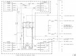
It appears you may be on the wrong diagram. Also looks like that picture I posted is a picture of K2..... I'm having him get a picture of K1. This is the diagram that should match our trucks:

K1K2.jpg
 

GeneralDisorder

Well-known member
Steel Soldiers Supporter
2,038
5,225
113
Location
Portland, OR
Questions:

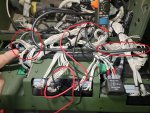
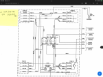
Need to see the wires connected to the K1 circled to the left. Picture and wire numbers.

Also - where the F is the large wire circled on the right going? That looks like it should be feeding K1 possibly?!?

61AA4A7B-CBE4-4FCB-AA36-0BA5B9167882.jpeg
 

GeneralDisorder

Well-known member
Steel Soldiers Supporter
2,038
5,225
113
Location
Portland, OR
Well I don't *think* it's that one but that's an interesting schematic - that looks newer than what I have as matching my truck. Also never seen these 24v "bussbars" it references. Here's the sheet data on mine (dated 08-29-2008 - the JPEG format compression has made it less readable than it is on my PDF):

TVSA1RGENIV.jpg

Yours looks newer because they have added things and also corrected the TL514 wire. On my schematic that is incorrectly identified as TL154 but the other end of it is TL515 so it's obviously a typo.
 
Last edited:

GeneralDisorder

Well-known member
Steel Soldiers Supporter
2,038
5,225
113
Location
Portland, OR
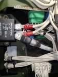
Ok. Can you get a better picture of the terminals on the K1 (left relay in the picture above)?

And I want you to fill out this form:

Left (K1) Relay:
30: (list wire numbers)
87: "

Right (K2) Relay:
30: "
87: "
 

GeneralDisorder

Well-known member
Steel Soldiers Supporter
2,038
5,225
113
Location
Portland, OR
after being taught by the general
K1 has 157 to 30
156 & 512 to 87

K2 has 514&150 to 30
151 to 87
Ok PERFECT. That's all exactly correct based on our schematics - Ronmar's even has the numbers correct that are typoed on my older diagram. We still need to verify that K1 doesn't have welded contacts though so we need to check for continuity with it out of the circuit. Pull 157 off of terminal 30 and check if there is still continuity between 30 and 87.
 
Top
AdBlock Detected

We get it, advertisements are annoying!

Sure, ad-blocking software does a great job at blocking ads, but it also blocks useful features of our website like our supporting vendors. Their ads help keep Steel Soldiers going. Please consider disabling your ad blockers for the site. Thanks!

I've Disabled AdBlock
No Thanks