Ok, lets start with the last one. K11 should NOT go click when when you pull it while running as it should be de-energized. It should go click when you turn on the ignition switch. 24v ign power flows thru CB77, and thru the neutral relay K26 energized contacts(30-87) to reach K11s coil. The TCM powers K26 when in neutral And K26 in turn powers K11 when in neutral.
The other side of K11s coil goes to the de-energized(30-87A) contacts of K40. K40 is controlled by the annunciator module and it energizes K40 above 350 RPM. This removes the ground to K11 which de-energizes it, which should shift power from CB77 to the alternator thru its 30-87A contacts. So with 24v ign applied, K26 and K11 energize.
in fact K11 MUST energize, as it is this same power from CB77 used for the alternator when de-energized, that powers the start switches via its 30-87 contacts when it is energized.
So when ign is turned on, the trans controller powers up in neutral energizing K26. K26 powers K11 and since the engine is not running, K40 provide a path to ground energizing K11. Once you start the annunciator powers K40, de-energizing K11 which disables the starter and brings the alternator online. Since the annunciator or K40 could fail, leaving the alternator offline, they backed things up by powering K11 thru the neutral start relay, so shifting out of neutral de-energizes K11 which then brings the alt online allowing you to complete the mission.
Either K11 is operating, or it has been bypassed to enable the starter buttons… if you can pull K11 out of circuit and it still starts, then the start circuit has been bypassed…
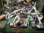
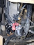
because of the use of the modular PDM boxes on the R, the most logical place to bypass the 24V ignition relay is at the relay itself. If the contacts are not fused, I suspect you will find both wires on one terminal, or otherwise connected together when the frame is lifted out of the dash To get to the relays. This is an A1 pic, but the R has the ign relays in the same place and they replaced the circuit board with modular PDM boxes.


 90.4 KB Views: 10
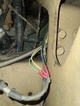 65.4 KB Views: 10
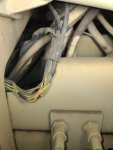 49.6 KB Views: 8
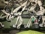
") I can see where mine have been chaffed/damaged/repaired in several spots.
I can see where mine have been chaffed/damaged/repaired in several spots.