• Steel Soldiers now has a few new forums, read more about it at: New Munitions Forums!

  • Microsoft MSN, Live, Hotmail, Outlook email users may not be receiving emails. We are working to resolve this issue. Please add support@steelsoldiers.com to your trusted contacts.

24v to 12v Without Converter or Transformer

224
1
16
Location
Independence, OH
There is, and always will be issues with parallel batteries. Unless the batteries are perfect or have special support circuitry... Any sort of voltage difference means current flow between the batteries. The limitation here is the internal resistance of the battery. As the batteries age any voltage difference will only increase. As lead acid batteries go through charge and discharge cycles the lead in the electrode plates of the batteries gets dissolved and re-deposited - but not uniformly. Eventually the plates fail and with parallel batteries that affects the good battery even more. Remember any voltage difference between the batteries means current flow. During charge cycles the battery with the lower voltage will take the bulk of the current flow, and during a discharge cycle the higher voltage battery provides most of the power. If one battery fails completely it may damage the other. Differential voltage problems are not limited to batteries. Heck, if you look at the old style power supplies with the brute-force regulators... The ganged output transistors have low value resistors placed on them to balance the outputs. As for adding diodes... Just remember that the average silicon diode has about 0.7 volt drop across the diode. If there were no voltage drop across the diode there would be no power dissipation at the diode and no reason for it to blow out.
 

swbradley1

Modertator
Staff member
Super Moderator
Steel Soldiers Supporter
14,270
1,782
113
Location
Dayton, OH
Just remember that the average silicon diode has about 0.7 volt drop across the diode.
Wow! That takes me back to when dinosaurs roamed the Earth and I learned the voltage drop across Germanium and Silicon diodes.

:)

Get a 24 to 12 converter.
 

FormerNewMVGuy

Active member
1,237
10
38
Location
stockton NJ
Any concern about heat build-up inside the can? Did you have to vent the can or use a fan to keep the converter cool?
Well i ventilated the can by drilling six 1/8th holes on each side just below the lid, I also added a toggle switch next to the 12 volt plug, So when im not using the inverter i can shut the power to it off.
The body of the inverter is setup as a heat sink, and after having it on for a couple of hours, it wasnt even warm to the touch, So i think the vent holes may have not been necessary...
I am really happy with this mod, BTW i used 14awg Mil wire that i got from saturn surplus.

The reason i went this route, was SWbradley posted the link in anther thread, Its the simplest way to go , and i got about 45 bucks into the mod.
 
Last edited:

rtbcoop

Member
58
0
6
Location
Tyndall AFB, FL
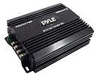
I started the thread more because I was curious than because I intended to use it. I figured someone else would have designed this way before me if it actually worked. I'll probably go with the ever popular Pyle. Anyone have problems using it with a speaker amplifier? Or better yet, any good 24v amplifiers? I am planning on doing the same sort of thing that you did with the ammo can except that I am going to drill my vents in the bottom of the enclosure. That way I can hook an air hose up to it, set around 2 psi. Keeps water out if I decide to go fording but still allows the enclosure to vent.
 
224
1
16
Location
Independence, OH
Make a drain to vent through and don't forget the flapper valve in the drain like the clutch... I've said over and over again I like relays for switching things. Hook the coil up to the accessory switch and you don't have to worry about switching it off. If you are getting electrical noise, there are things that can be done to clean that up... No worries.
 

Tow4

Well-known member
Steel Soldiers Supporter
2,098
657
113
Location
Orlando, FL
Just tap off the battery(s) that goes to ground so you have 12V from B+ to ground. If you are worried about charge imbalance, switch the battery position every 6 months. I swap my CUCV batteries front to back like that and have no problems. If you are going to pull more than about 5 AMPS I would go the 24V to 12V voltage reducer route.
 

Speedwoble

Well-known member
606
302
63
Location
New Holland, PA
The CUCV's have separate alternators for each battery. If you try to tap a single battery on the deuce with a load of any significance, you will kill the battery in less than 6 months.
 
748
5
18
Location
Woodstock, GA
Thanks for the heads up on the inverter, however the revues of this product are not 100% +ve....... 5:2 fore/against.
Just thought I'd add this incase people jumped without reading the revues.

I'm going with a small car alternator...
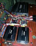
I have two of these Pyle 720 watt converters in my M35A3 and I swear by them (not at them). This topic seams to come up all the time and I am always pushing the inverters because they are cheap, easy, and work very well. rThey put out a lot of power too. See the build thread link in my signature for more details. BTW, I bought mine for about $22/each a year ago so you may want to check that website periodically to see if you can get a better deal than they are offering now. A 12V alternator is overkill in most cases unless you plan on running a 12v winch.
 

Attachments

DUG

Senior Chief/Moderator
Super Moderator
Steel Soldiers Supporter
2,799
73
48
Location
Mesquite, NV
I'm a fan of overkill - I love the dual alt setup. And having an extra battery has already saved me once when one of my main batteries died. I was able to swap it with the 12 volt side and get going quickly.
 
194
2
16
Location
Norfolk, VA
What are you guys using for a disconnect relay? 720w at 24v is 30A The only reasonably priced option I have found that supports that is an Altronics RB30 http://www.altronix.com/products/product.php?name=RB30 which would need some sort of enclosure. I know that the 720w is the rated peak capacity, but I would prefer not to be burning out and replacing relays all the time by over powering a 15A model. I've also considered utilizing a continuous duty solenoid, but I haven't been able to locate a suitable one of those yet either.
 
748
5
18
Location
Woodstock, GA
What are you guys using for a disconnect relay? 720w at 24v is 30A The only reasonably priced option I have found that supports that is an Altronics RB30 http://www.altronix.com/products/product.php?name=RB30 which would need some sort of enclosure. I know that the 720w is the rated peak capacity, but I would prefer not to be burning out and replacing relays all the time by over powering a 15A model. I've also considered utilizing a continuous duty solenoid, but I haven't been able to locate a suitable one of those yet either.
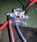
You need a solenoid switch. I got mine on amazon or ebay from a company in middle GA. It is 24v and I think 100A. If you can't find one online let me know and I'll dig up where I got mine from. Mine is pictured below. It lets me kill all my accessories with 1 switch on the dash.
 

Attachments

224
1
16
Location
Independence, OH
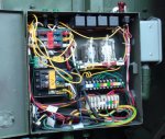
Err... I picked up some 24V relays at a - local Cleveland - place called Electronics Surplus. There were three sets of contacts rated at 10 amps in each relay. Figured 30 amps would be plenty for my modest needs. Don't remember the price but they were definitely under $10 each. ( They are the two zip tied thingys under the black bank of headlight relays. )
 

Attachments

748
5
18
Location
Woodstock, GA
Err... I picked up some 24V relays at a - local Cleveland - place called Electronics Surplus. There were three sets of contacts rated at 10 amps in each relay. Figured 30 amps would be plenty for my modest needs. Don't remember the price but they were definitely under $10 each. ( They are the two zip tied thingys under the black bank of headlight relays. )
If someone is choosing to use the 720w/30A Pyle converter, then I would suggest installing a relay, solenoid, or breaker (rated at 30A or greater) before the converter so that it isn't powered when not in use. I like the 100A solenoid because I have two of the converters (30A + 30A = 60A) and my off road lights (run at 24V out of the same distribution block that powers the converters for another 8 lights * 4.58 = 36.64 Amps) for a total of 96.64 Amps. Your best choice really depends on what your needs, or future needs, may be. I did install 6 relays for my off road light circuits; so I'm not opposed to them.
 

MarcusOReallyus

Well-known member
4,524
818
113
Location
Virginia
I may be missing the point of original post, but if you just want a moderate amount of 12 volt off 24 volt series system, can't you tap off the back of the first battery, as is done in CUCVs for the 12v part of the system? (except 1010)

Yes, you can, but you can also wind up with batteries that are imbalanced, that is, charged unequally. Bad things happen. If they are too far out of whack, you can have serious charging problems.
 

phil2968

Active member
2,591
18
38
Location
Lakeland, Florida
Cucv's also have two alternators that keep both batteries fully charged. So pulling from one does not effect the system the way it would in a deuce.
 

MarcusOReallyus

Well-known member
4,524
818
113
Location
Virginia
Why it doesn't work, and other smoke generating topics...

Yeah, I know all the other options, was more curious why this WOULDN'T work. Frying the diodes is a good point; not sure if they make high-load diodes...
I think I see where you were going, and it's a nice try, but no cigar this time. Let's look at why it doesn't work.


First, let's review basic diode theory. Diodes are like one-way valves in an electric circuit. If current is flowing through them in their "forward" direction, they are almost a short circuit. Very low resistance. In the other direction, the "reverse" direction, they are almost an open circuit. (There's always a little leakage. We can ignore it for now.)

Let me quote another website here:

Diodes exhibit a low resistance to current flow in one direction and a high resistance to current flow in the other. The direction in which the current flows is referred to as the forward direction while that in which negligible current flows is known as the reverse direction. When a diode is conducting, a diode is said to be forward biased and a small voltage (ideally zero) is dropped across it. This voltage is know as the forward voltage drop.

Now let's look at the diode symbol. It sort of looks like an arrow, pointing into a wall. ---->|----

The arrow shows the forward direction of current. If there's 12v here ---->|---- and ground is on this side, current flows. The current hits the arrow and punches it through the wall.

However, if we reverse that: 12v ----|<---- ground Now no current flows. The current hits the wall and stops. That "arrow punching through the wall" thing helps me remember which way is which.


So let's look at your diagram (with some new labels, and a minor correction to the diode symbol):


12v out of 24v.jpg


  • Diode #1. He's connected to 0v (ground) on both sides of him. No current can flow. He might as well not be there - he's doing nothing useful. Sort of like.... oh, no, I won't make any political jokes. :mrgreen: "But what about the current from Diode #3?" We'll get there. Hold on.


  • Diode #2. At first glance, it looks like this guy is forward biased (turned ON) to provide a current flow to your "12v" point. Seems reasonable, but wait, we have to consider Diode # 4. We'll get to him and then talk about his effect on #2.


  • Diode #3. I have no idea what he was supposed to do, but he ain't doin' it! He's connected on one side to 12v (the - terminal of Batt 2 is connected to the + terminal of Batt 1) and the other side to ground. If he were forward biased (turned ON), you'd have pretty close to a dead short to ground.To quote one of my professors, commenting on one of my exams, "I smell smoke!" :mrgreen: But he's not, he's reverse biased (turned OFF), so nothing is happening. Cut the wire and you'd have essentially the same thing. Nada.


  • Diode #4. Oh, aren't we clever! This is how you plan to get 24v AND 12v from both batteries! Nope. Ain't gonna work. # 4 is forward biased for 24v to flow to that "12v" point in your diagram. That's 12v more positive than the 12v you thought you had there from Diode #2. So, #2 is actually reverse biased (turned OFF), leaving you with current flow from the 24v terminal to whatever loads are connected to that "12v" point in your diagram. It ain't 12v at that point, it turns out to be 24v. Oops. So, depending on the current rating of that diode, the amount of load you have on that part of the circuit, and the voltage tolerance of the devices connected to it, you just might get some smoke out of that machine. :D


But what you will NOT get is 12v AND 24v drawn from BOTH batteries.

Clear as mud? :beer:
 
Top
AdBlock Detected

We get it, advertisements are annoying!

Sure, ad-blocking software does a great job at blocking ads, but it also blocks useful features of our website like our supporting vendors. Their ads help keep Steel Soldiers going. Please consider disabling your ad blockers for the site. Thanks!

I've Disabled AdBlock
No Thanks