• Steel Soldiers now has a few new forums, read more about it at: New Munitions Forums!

  • Microsoft MSN, Live, Hotmail, Outlook email users may not be receiving emails. We are working to resolve this issue. Please add support@steelsoldiers.com to your trusted contacts.

303M HydraMatic rebuild

rustystud

Well-known member
9,136
2,665
113
Location
Woodinville, Washington
There are differences between civilian and military units. The front pump is "not" one of them though. All HydraMatics came with the 7 vane front pump. That being said there is a surprise I'm going to post here later.
The rear pump is the same also except for the line going to the reduction unit. So it has a different housing.
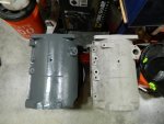
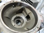
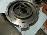
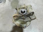
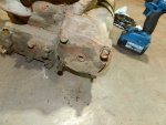
Also the "main" housing is very different as you can see here. The left housing is a Pontiac and the right is the 303M housing.
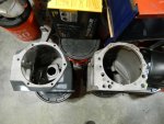
007.JPG011.JPG
A major difference is in the 2 main clutches. The pistons use a solid seal ring instead of a rubber "lip seal".
I can only guess the military wanted no possibility of clutch failure due to overheat melting the lip seal or the lip seal leaking due to a tear caused by debris in the fluid or pieces of friction material causing a tear.
This means you cannot use rubber lip seals on these units without some machine work.
Also, all military units came with a 4-pinion planetary instead of the standard 3-pinion planetary.

About the crack. No it cannot be safely welded up. It is in a high stress area and would only crack again.
I can say this due to the fact I was a welder for 10 years and cast iron was one of the metals I welded on a regular basis. That and Aluminum and Stainless Steel. I did weld "black Iron" , but that work was usually welded by another Welder who did nothing but weld "Black Iron" all day long. I at least got a break and could play with other metals.

About running in "high reverse" . High gear in the reduction is nothing more than a 1:1 output. So basically it means your running a "Normal" transmission or from Military's point of view, your running the "301MG" transmission.
The reduction unit just has 2 ratio outputs. Low and High, (high meaning a regular 1:1 output) .

Now there is a problem with a "normal" HydraMatic transmission. They have excessive internal leakage, so the oil pumps must work very hard in normal conditions to keep up with the "normal" loss of pressure. That is one reason the 303M transmission has 3 oil pumps. The front pump, the main body rear pump and the reduction units rear pump. That is one of the reasons this transmission runs so hot and needs that oil cooler. All fluid once it is pressurized gets hot from that process. Air does the same thing. Ever touch the return line on your air compressor after it has just run ? It will burn your hand. Oil does the same thing.

These issues where addressed in later HydraMatics. The use of "rubber seals" in ALL clutches for one.
 
Last edited:

rustystud

Well-known member
9,136
2,665
113
Location
Woodinville, Washington
Some people have wondered about the operation of the reduction unit. So I'll try and explain it here.
This transmission (The HydraMatic) was basically the "first" truly automatic transmission made.
That being said they didn't know how most mechanical and hydraulic issues should be delt with. There was no specifications book to look up things in. They wrote the book !
So the parts in this transmission are over built to say the least ! We know at this time Aluminum housings are fine for large transmissions. Just look at any Allison transmission out there. Though some of the first Allison transmissions where in fact cast iron. The MT series are a good example. They learned you didn't need all that cast iron.
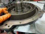
But the people at the HydraMatic division didn't know that then. So take a look at the reduction's unit low piston.
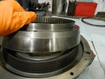
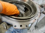
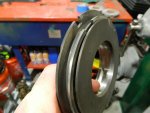
042.JPG It is over 13" across ! and weighs in at about 20Ibs. It fits in the "output shaft bearing retainer" housing. When pressure is applied to this piston it moves upward and the friction surface which is built into the piston (see my hand) contacts the "driven cone" seen here.
044.JPG

(First off everyone needs to know there are 2 output shafts in this transmission to understand the operation of the gear set.
The "main housing" output shaft" and the "reduction unit" output shaft. Now back to the piston and the driven cone.)

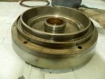
This "driven cone" then slides up on the "reduction unit clutch housing" seen here,
047.JPGand contacts the "stationary cone" which is pressed into the reduction units housing. You can see the friction material in that wedge shape at the end of the housing. The pressure of the piston sandwiches the "driven cone" making it stationary with the reduction housing. Basically holding the cone.
045.JPG046.JPG

Now everyone needs to remember that you need 3 reactions to make a planetary gear set work.
You need a "driven" input, a holding force and a output. So for example, you drive the sun gear, hold the planetary gear and the ring gear rotates for the output.

In this case the "driven cone" is holding the ring gear which is stopped. Since the sun gear is splined to the main housing output shaft it forces the planetary gear set which is attached to the reduction unit output shaft to spin at a reduced rate compared to the speed of the sun gear or main housing output shaft.

For high gear or really 1:1 the "direct clutch piston" which is in the clutch drum moves upward and locks into the ring gear but since the direct clutch housing is locked to the main housing output shaft is causes the ring gear now to be the driven force being locked to the output shaft. Since the sun gear is also splined to this output shaft the planetary gear which is splined to the reduction units output shaft is forced to be in a 1:1 ratio with the main housing output shaft. Basically, everything is locked up.

All this could be built into a unit that is less than 1/4 the size today. So like I said earlier this unit is way over built and extremely heavy ! and it takes a lot of fluid to fill that piston cavity.

I don't know if I made this easier to understand or not.
 
Last edited:

m1010plowboy

Well-known member
Steel Soldiers Supporter
3,834
2,475
83
Location
Edmonton, Canada
I don't know if I made this easier to understand or not.
You'll need to type slower for the landscapers and Canadians but I'll PM you when I get more question.

I learned more, reading that post, than all the manuals I read in the hot tub. Awesome description.


CONTROL VALVE

Control valve function will be a topic. You'll get there and when you do, I'll try to remember the little lever that would get hung up over time and cause shifting problems. The repair was real simple. I was busy thinking about trees and sod so didn't pay attention but removing, cleaning and replacing the control valve was a regular thing for Gold mining mechanic Gary.

Everything was trying to keep me from hitting the Post office yesterday. Late sod, rain, cold, wind, overtime..........and then this at the UPS store today. Didn't think I'd get it done.

P6012335.JPG

Last time I tried Canada Post they had a new funky style lockdown system where folks needed to sign in with a Smart Phone. I don't like that but stopped by to see if they changed their attitude. Today, this fine lady was standing outside Canada Post and said, "We lost 3.3 Billion dollars last year so come on in spend Rustystud's money." It was a high pitched voice so if you're reading this it's best if you can imagine screeching.

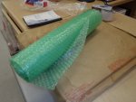
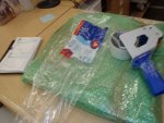
The 40cmx40cm box didn't fit a package so the girl on the wall wrapped it in bubble wrap for $4.99. Nuts...... Should be dry and complete when you get it.

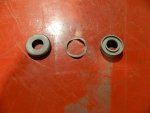
It's basically seals, gaskets and a tiny little fabric style oil seal looking thing no bigger than a lady bug.

I'll PM the tracking number.

P6012336.JPGP6012338.JPGP6012339.JPG
 

rustystud

Well-known member
9,136
2,665
113
Location
Woodinville, Washington
You'll need to type slower for the landscapers and Canadians but I'll PM you when I get more question.

I learned more, reading that post, than all the manuals I read in the hot tub. Awesome description.


CONTROL VALVE

Control valve function will be a topic. You'll get there and when you do, I'll try to remember the little lever that would get hung up over time and cause shifting problems. The repair was real simple. I was busy thinking about trees and sod so didn't pay attention but removing, cleaning and replacing the control valve was a regular thing for Gold mining mechanic Gary.

Everything was trying to keep me from hitting the Post office yesterday. Late sod, rain, cold, wind, overtime..........and then this at the UPS store today. Didn't think I'd get it done.

View attachment 924839

Last time I tried Canada Post they had a new funky style lockdown system where folks needed to sign in with a Smart Phone. I don't like that but stopped by to see if they changed their attitude. Today, this fine lady was standing outside Canada Post and said, "We lost 3.3 Billion dollars last year so come on in spend Rustystud's money." It was a high pitched voice so if you're reading this it's best if you can imagine screeching.

The 40cmx40cm box didn't fit a package so the girl on the wall wrapped it in bubble wrap for $4.99. Nuts...... Should be dry and complete when you get it.

It's basically seals, gaskets and a tiny little fabric style oil seal looking thing no bigger than a lady bug.

I'll PM the tracking number.

View attachment 924840View attachment 924841View attachment 924842
Thanks Dave for all your help in this project. For those who don't know, plowBoy Dave is supplying the gaskets and seals I will need to complete this rebuild.
 

rustystud

Well-known member
9,136
2,665
113
Location
Woodinville, Washington
Thanks for documenting this. Talk about a lost art. At some point in this thread can you hypothesize what reduction unit components get stuck together when you have the dreaded lockup in high range.
I can tell you right now what happens when this "dreaded lockup" occurs. That large 13" diameter piston is hanging up due to a slow drain down on release. I was going to show people how to fix this tonight in fact.
 
Last edited:

rustystud

Well-known member
9,136
2,665
113
Location
Woodinville, Washington
OK I already spilled the beans on tonight's topic. The "dreaded lockup" in high gear.
The apply port for this piston is extremely small. The only reason I could imagine they did this was to prevent a hard apply of the piston. What they really did was limit the time the fluid had to apply the piston which can cause slippage, and the extremely slow release of this piston due to the fact they only provided this one hole. "One hole to fill, one hole to drain. One hole to rule them all !!! " OK sorry about that .
Here's what I'm talking about.
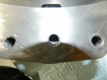
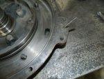
143.JPG145.JPG This hole fills and drains this large reduction piston. This hole is actually smaller than what you see here as I had already drilled it out in these pictures !!!

I dug out this housing that I haven't drilled out yet. It has a 3/16" hole !
018.JPG
I drilled it out to a 1/4" hole. Any larger and you run the risk of not being able to seal the housing. I do have an extra casting so maybe I might play with it and see how large I can go. I think I can get away with a 5/16" hole. The problem is the angle of the hole. The drill cuts very close to the edge of the housing.

One of the major problems I'm facing in this rebuild is acquiring this gasket that seals the reduction unit.
I have not found one anywhere. "Fatsco" is the only company making any parts for the old HydraMatics and they make "nothing" for the military 303M unit. So I'm left with just using a silicone product or a gasket maker like product. The problem is things like this apply hole. It has up to 300 PSI at times. I'm afraid it will blast through any flimsy product I try to use.
I'm going to be talking with the machinist I use to see about cutting a small circle in the housing for a "O" ring to fit into. An "O" ring with gasket maker just might do the trick. We will see.
 
Last edited:

rustystud

Well-known member
9,136
2,665
113
Location
Woodinville, Washington
I was reading the old thread "HydraMatic Heaven" and a lot of the information about shifting is true, but the information about oil is not. The reason people seem to find the transmission works better with a heavier viscosity fluid is that the "Military" HydraMatic from the factory leaked internally like a sieve !!!
They used solid seal rings on the apply pistons instead of rubber lip seals. These seal rings leave a large gap in use and fluid just pisses out of them. There are other areas fluid just pours out internally also.
The correct fluid has always been Dexron. The planetary rollers have extremely small needle roller bearings which will not be lubricated properly with a heavier viscosity fluid.
I'm going to show you how I will fix this problem in my rebuild later on.
 

rustystud

Well-known member
9,136
2,665
113
Location
Woodinville, Washington
You'll need to type slower for the landscapers and Canadians but I'll PM you when I get more question.

I learned more, reading that post, than all the manuals I read in the hot tub. Awesome description.


CONTROL VALVE

Control valve function will be a topic. You'll get there and when you do, I'll try to remember the little lever that would get hung up over time and cause shifting problems. The repair was real simple. I was busy thinking about trees and sod so didn't pay attention but removing, cleaning and replacing the control valve was a regular thing for Gold mining mechanic Gary.

Everything was trying to keep me from hitting the Post office yesterday. Late sod, rain, cold, wind, overtime..........and then this at the UPS store today. Didn't think I'd get it done.

View attachment 924839

Last time I tried Canada Post they had a new funky style lockdown system where folks needed to sign in with a Smart Phone. I don't like that but stopped by to see if they changed their attitude. Today, this fine lady was standing outside Canada Post and said, "We lost 3.3 Billion dollars last year so come on in spend Rustystud's money." It was a high pitched voice so if you're reading this it's best if you can imagine screeching.

The 40cmx40cm box didn't fit a package so the girl on the wall wrapped it in bubble wrap for $4.99. Nuts...... Should be dry and complete when you get it.

It's basically seals, gaskets and a tiny little fabric style oil seal looking thing no bigger than a lady bug.

I'll PM the tracking number.

View attachment 924840View attachment 924841View attachment 924842
I'll address that issue soon, with pictures !
 
Last edited:

rustystud

Well-known member
9,136
2,665
113
Location
Woodinville, Washington
OK here's a little "trick" to help with the apply of the front and rear clutch packs.
You have a lathe cut a 1/16" deep ridge on the bottom of the apply piston. Extend it 1/2" outward from the center of the piston. See picture.
img002.jpg This allows a faster apply of the clutches since there is already a "surface" for the fluid to push against instead of the fluid trying to get under the piston before it can push against it.
This is one of those "old timers" tricks I learned.
 

USMC 00-08

Well-known member
1,171
156
63
Location
Skiatook, OK
Is the reduction unit gasket included in the set Plowboy is sending you? If so, how willing do you think Fatsco would be to duplicate any/all of the gaskets needed or start producing parts specific to this transmission?

Thank you for posting all this knowledge! We probably need to make this thread a sticky when you get through.
 

rustystud

Well-known member
9,136
2,665
113
Location
Woodinville, Washington
Is the reduction unit gasket included in the set Plowboy is sending you? If so, how willing do you think Fatsco would be to duplicate any/all of the gaskets needed or start producing parts specific to this transmission?

Thank you for posting all this knowledge! We probably need to make this thread a sticky when you get through.
I don't know if that gasket exists anymore. I'm hoping it comes in the kit, but I'm not holding my breath.
As far as anyone reproducing parts for our 303M I don't holdout any hope. I talked with the Fatsco representative, and he said there needs to be a pretty good demand for any item to be "repoped" . Our 303M is such a rare creature no one would invest that kind of money for retooling to make our parts.
I do have numbers for the 3 roller bearings and they recently came in the mail. So bushings can be made in a machine shop, as can thrustwashers. The clutch plates are sold by Fatsco, except for the ones in the reduction unit. Thankfully those are "Bronze" and usually are in good shape. So the only parts we need are the gaskets and the lip seals (for the two large pistons) in the reduction unit.
I'm looking into a company that sells kits that would allow a person to make their own seals. Just need to find the right seals.
 

rustystud

Well-known member
9,136
2,665
113
Location
Woodinville, Washington
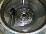
OK, tonight I finish tearing down the reduction unit.
002.JPG There's not a lot of things to remove on this, but you do need to check them.
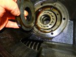
First off the rear seal must be removed to access the snap-rings. There are two. One holds in the output shaft and the larger one holds in the rear bearing. Remove both.
004.JPG005.JPG006.JPG
After that is done, I put a couple of shop rags under the housing to catch the output shaft/planetary unit.
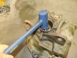
Then taking a dead blow hammer, give the shaft a good whack or three.
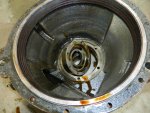
009.JPG Now turn over the housing and start on the rear pump. The first item to remove is the bearing support. Three bolts and it's out.
010.JPG Then remove the rear pump bolts and remove the pump cover and gears. The pump housing will come out also, though sometimes you will need to give it a nudge from the other side.
012.JPG014.JPG015.JPG
Remember to keep the pump gears together the way they came out and in the proper orientation. Facing up or facing down. I would clean them up and use a magic marker to help you remember.
Now we take off the "accumulator". I pull out two bolts and then thread them back in 1/2" . This gives me a safety margin in case the snap-ring is broken. If the snap-ring is broken the accumulator can come flying out of the housing once you remove all the bolts. It has happened to me once. That spring went flying out like crazy !
013.JPG
The reduction unit is basically tore down at this point except for the valve body. Since this unit is a spare, it is going to get stored away and there is no reason to remove the valve body.
The valve body gaskets are another item that we will need to get made up.
 

lpcoating

Well-known member
Supporting Vendor
370
674
93
Location
Mansfield, PA
I don't know if that gasket exists anymore. I'm hoping it comes in the kit, but I'm not holding my breath.
As far as anyone reproducing parts for our 303M I don't holdout any hope. I talked with the Fatsco representative, and he said there needs to be a pretty good demand for any item to be "repoped" . Our 303M is such a rare creature no one would invest that kind of money for retooling to make our parts.
I do have numbers for the 3 roller bearings and they recently came in the mail. So bushings can be made in a machine shop, as can thrustwashers. The clutch plates are sold by Fatsco, except for the ones in the reduction unit. Thankfully those are "Bronze" and usually are in good shape. So the only parts we need are the gaskets and the lip seals (for the two large pistons) in the reduction unit.
I'm looking into a company that sells kits that would allow a person to make their own seals. Just need to find the right seals.
We have a CNC router with a knife head option. If I had a gasket (or part) to copy, we could probably make gaskets.
 

rustystud

Well-known member
9,136
2,665
113
Location
Woodinville, Washington
We have a CNC router with a knife head option. If I had a gasket (or part) to copy, we could probably make gaskets.
You can ? That would be fantastic ! I don't have any original gaskets as they all got destroyed upon disassembly, but I have the housings. I have to figure out how much it is going to cost to ship that 50Ibs bearing retainer to Mansfield PA from Seattle WA.
How far are you from "plowboy" ? He has these part I believe.
Also there are several small gaskets that are not in the kit, like the reduction assembly valve body and the reduction rear oil pump. Those would be easy to send to you.
I'll PM you and see if we can't come up with some solutions !
 

rustystud

Well-known member
9,136
2,665
113
Location
Woodinville, Washington
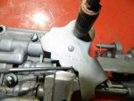
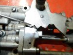
Plowboy mentioned the valve body having issues. The reason for that is the Military decided to change the shift lever detent system. Why ? I can only guess they didn't want any possibility of it jumping out of gear in rough terrain. It is more positive this way as you can see, but terribly difficult to shift.
021.JPG022.JPG You can see how they made the detent pin into a "triangle" shape with corresponding triangles in the shift lever. Really fits snug. No possibility of it "jumping" out of gear, but you cannot shift it by hand here. It takes a small screwdriver pushing in the detent plunger to be able to move it. Over time this can cause some serious wear on the valve body core where the shift lever rotates in.

026.JPG I know it's upside down but you can clearly see the nice "rounded" plunger and lever slots. It shifts so nice too.
The fix, if your shift lever is causing you grief is to grind the triangle shaped plunger into a nice rounded shape. Also the lever needs some "dremal" work to allow the new plunger shape to fit into. Or you can try and find a valve body out of any old HydraMatic and swap out the plunger and lever.
 
Last edited:
rustystud

Well-known member
9,136
2,665
113
Location
Woodinville, Washington
On a different note, don't lose these small parts that mount on the outside shift lever .
001.JPG They create a water proof seal for the shift and throttle levers. The HydraMatic is an extremely waterproof transmission with the exception of the shift and throttle levers. These little buggers solve that. There is also a wave spring and rubber gasket that fits on the inside of the valve body pan.
 

rustystud

Well-known member
9,136
2,665
113
Location
Woodinville, Washington
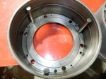
Now is as good a time as any to share a little secret to help beef-up this transmission. The two main drums, the front clutch drum and rear clutch drum are not as strong as they could be. In later HydraMatics they fixed this issue. So what am I talking about. Here's a picture of the standard drum.
199.JPG You can see that there are three rods that hold the steel plates. Lets call those rods "torque rods" as that is what they do. When energized this clutch pack transmits it torque through those three "torque rods". What happens under stress is the steel plates can "warp" since they only transmit torque through those three rods.
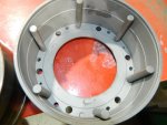
200.JPG This is a later design clutch drum. Same exact exterior and interior dimensions as the earlier one, they just added three more "torque rods" . What this does is "spread out" the torque load on the steel plates and the drum housing itself.
You can find these drums in any Cadillac, Pontiac, Oldsmobile HydraMatic .
Both front and rear drums have this feature.
An interesting note about these drums is that it allows you to use less friction and steel plates to accomplish the same torque load as the earlier design drums.
Since we want more capability out of the clutch drums, we will still use the same amount of steel and friction plates. The early "Hot Rod" community found out about this and utilized it when racing these transmissions.
Someone might ask then, since the drum designs are all the same then how do you get different amounts of friction and steel plates in the drums. The answer is the "clutch pistons" . They are different thickness for different applications. The military used the maximum number of plates possible, while an Oldsmobile would only need say 5 or 6 friction and steel plates. So the military 303M transmission has a very thin clutch piston while the Oldsmobile has a very thick clutch piston.
205.JPG
 

lpcoating

Well-known member
Supporting Vendor
370
674
93
Location
Mansfield, PA
You can ? That would be fantastic ! I don't have any original gaskets as they all got destroyed upon disassembly, but I have the housings. I have to figure out how much it is going to cost to ship that 50Ibs bearing retainer to Mansfield PA from Seattle WA.
How far are you from "plowboy" ? He has these part I believe.
Also there are several small gaskets that are not in the kit, like the reduction assembly valve body and the reduction rear oil pump. Those would be easy to send to you.
I'll PM you and see if we can't come up with some solutions !
Hello. Per my PM back to you, if you (or someone else) can provide a tracing of the gasket from the part, we can scan that and create a dxf file for our router. Maybe use a heavy paper and a accurate tracing and I think we'll be business.

Guy
 
Top