• Steel Soldiers now has a few new forums, read more about it at: New Munitions Forums!

  • Microsoft MSN, Live, Hotmail, Outlook email users may not be receiving emails. We are working to resolve this issue. Please add support@steelsoldiers.com to your trusted contacts.

303M HydraMatic rebuild

rustystud

Well-known member
9,298
3,077
113
Location
Woodinville, Washington
I was going to install the "Accumulator" assembly today, but it needed work. So I was forced to tear it down. I know I said to leave it alone if you could, and believe me I wished I had left it alone but it needed to come apart.
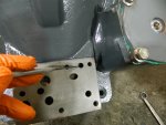
The "accumulator piston" is supposed to have a "slight" press fit into the "pin" but this bugger was totally seized on the pin !
It took my 10 ton press to get it off and the springs shot out and just caught my right hand. Now I have a nice purple bruise on my right hand ! By tomorrow it should be a real dousy of a bruise !
Stupid springs !!! Stupid me for taking it apart !!!!

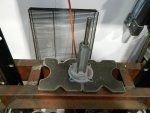
007.JPG
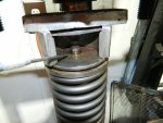
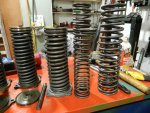
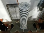
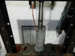
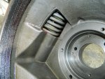
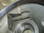
You can see the fully extended springs here compared to the compressed ones.
009.JPG
The reason I had to take it apart was the "piston" had severe rust on the edges and since it needs to slide smoothly in it's bore it needed to be replaced. The other accumulators all have pretty heavy rust and need to come apart to be sandblasted. I took the piston off one of the accumulators that had a broken bolt flange, but the piston was good.
Going back together will be lots of fun too !!!
 

Attachments

Last edited:

rustystud

Well-known member
9,298
3,077
113
Location
Woodinville, Washington
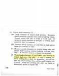
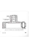
For those who question whether the output shaft needs that bushing, here's the TM 9-8025-2 manuals answer for that.

img031.jpgimg030.jpg
So far on six 303M transmissions I have torn down this year. None had this bushing installed.
I truly believe the "factory" screwed up here. So every military rebuilder afterwards didn't even look for a bushing here since these two pages (160 and 161) are the only place in the whole manual even mentioning this bushing. Civilian mechanics would have known there was supposed to be a bushing here, like I did.
I'm pretty disappointed in the quality and layout of this manual. It's like a child put it together. Or an absent-minded person. There is no clear line of disassembly or reassembly. There are parts I know I read but after looking for hours I cannot find that passage again. Really makes me mad as I was going to mark this one page but thought I'll do it tomorrow as I was tired and wanted to go to bed.
I'll find it, but I shouldn't need to try and find information like that. Civilian manuals are clear and precise. They of course need to be as the mechanics would lose the company money if they needed to find information and had to spend hours trying to find it.
Of course, my observations are five decades to late !
 

rustystud

Well-known member
9,298
3,077
113
Location
Woodinville, Washington
I see I forgot to show "how" to disassemble and reassemble the Accumulator, so I'll do that now.

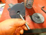
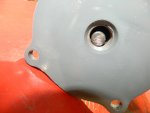
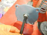
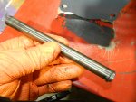
To disassemble the Accumulator you first need to remove the pipe plug on the cover. Than you need to install a 4" rod. The book says to use a 3/8" rod. I had a 1/2" rod and it's much safer in my opinion.
017.JPG022.JPG023.JPG
Put the pipe plug back in and then go to your press. Using whatever you have on hand to press the piston down, press it down just enough to free the "snap ring" . Remove the accumulator from the press.
Now you need to remove the 4" rod and put the accumulator back in the press. You will need something to push the "Piston Pin" down. I used a long 7/16" socket. You will need to totally compress the springs. Once the springs are totally compressed you need to push the piston pin out. It might take some force, just be forewarned.
Once the pin is totally pushed out the springs will rebound up. Take care here. Then it's just a matter of removing the accumulator out of the press.

To reassemble the Accumulator , you need to make sure one end of the piston pin still has it's snap ring on. This end goes down.
018.JPG
Then install the 4" rod and install the pipe plug. With the cover assembly and piston pin installed put it back in the press. Install the springs and put the accumulator piston on top.
025.JPG026.JPG029.JPG
Lube the top of the pin and press the piston back on. Be very careful to align the pin and piston. Once it starts in the hole you can then get busy forcing it back on. Do not push past the snap ring groove !
016.JPG
Install the snap ring and remove the accumulator from the press. Now remove the 4" rod and put the accumulator back in the press. You now need to "seat" the snap ring. Pressing on the pin, totally collapse the springs and push the pin down until it sits firmly on the piston. Remove the accumulator.
Your done !
 

Attachments

rustystud

Well-known member
9,298
3,077
113
Location
Woodinville, Washington
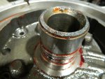
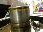
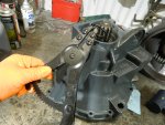
I forgot to mention when checking the components of the 303M transmission to really take a good look at the snap ring groove on the "output shaft bearing retainer" . This groove can easily get damaged. Also it is a weak link in the system until everything is assembled.
I've found several assemblies that had bad or damaged grooves. Including the one that broke on me.
It had already started to crack and when I tested the reduction piston without having a ring installed to hold the piston in, the groove took the full force of the piston and broke totally off.
007.JPG
The assembly could have lasted for years to come, or broke off after a week of use. We'll never know now.
I guess I'm better off having it break now.

On this part you can see the previous rebuilders had to repair the groove by "brazing" the cast-iron and then remachine the shaft. I don't like that and will not be using this part.
003.JPG006.JPG
 

rustystud

Well-known member
9,298
3,077
113
Location
Woodinville, Washington
I finished installing the accumulator in the housing today. I also installed one in another case.
I plan on rebuilding three 303M transmissions before this spring.
At this time, I don't know how long we will be able to keep the 303M transmissions operating. With parts almost nonexistent it's just a few years before there will be no more 303M transmissions.

With that in mind I'm having my machinist friend looking into "refabing" parts that experience heavy wear and damage on them.
Parts like the "oil delivery sleeve" and the "rear bearing support" assembly and of course the front pump's "vanes" .
GM on it's Turbo 400 transmission had cast-iron housings that had pressed in "steel" parts. The front pump is a prime example. The "stator support" was made out of steel while the pump housing was made out of cast-iron.
The steel section was made replaceable due to extreme wear.
If the large casting of the "rear bearing support" could have its center support machined out and a steel replacement pressed in that would be a game changer. No more broken snap-ring grooves for one.
Also the "oil delivery sleeve" could easily be made out of 4140 steel.
I'm taking a sample down to the machinist next week.
The front pump "vanes" should also be an easy part to machine. They will need to be heat treated afterwards though.
With gaskets and oil lip seals and sealing rings still being made, and clutch plates still being made, and bands being relined, all that is needed is a few oil lip seals and some sealing rings made up.
We'll see.

Here's the pictures of the accumulators being installed and tested.

001.JPG002.JPG

Apply air pressure here to actuate the accumulator.
003.JPG
This is the accumulator in its released position.
004.JPG
This is the accumulator with air pressure applied.
005.JPG
There should be no leaks.

Just a side note here.
I need to mention some problems the "Accumulators" have.
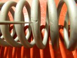
One is wear on the springs. Due to either stress or in this case rust.
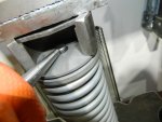
You can see the rust has eaten into the large outer spring shown here.
008.JPG
Since the rust has gone around the spring, it has created a severe weak spot, and the spring can break here.
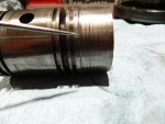
Another area is the piston. The pistons outer edge needs to be nice and smooth to glide along the bore.
This piston has been eaten by rust and destroyed the outer edge. Excessive wear can also destroy the edge.
005.JPG007.JPG
Normally I do not have to mention rust in an automatic transmission, but since we have to deal with old transmissions laying outside to get parts to rebuild our own transmissions, rust has become a major issue.
Both these parts have to be thrown out.
 
Last edited:

DUUANE

Active member
434
189
43
Location
Qualicum Beach BC
For those who question whether the output shaft needs that bushing, here's the TM 9-8025-2 manuals answer for that.

View attachment 936406View attachment 936407
So far on six 303M transmissions I have torn down this year. None had this bushing installed.
I truly believe the "factory" screwed up here. So every military rebuilder afterwards didn't even look for a bushing here since these two pages (160 and 161) are the only place in the whole manual even mentioning this bushing. Civilian mechanics would have known there was supposed to be a bushing here, like I did.
I'm pretty disappointed in the quality and layout of this manual. It's like a child put it together. Or an absent-minded person. There is no clear line of disassembly or reassembly. There are parts I know I read but after looking for hours I cannot find that passage again. Really makes me mad as I was going to mark this one page but thought I'll do it tomorrow as I was tired and wanted to go to bed.
I'll find it, but I shouldn't need to try and find information like that. Civilian manuals are clear and precise. They of course need to be as the mechanics would lose the company money if they needed to find information and had to spend hours trying to find it.
Of course, my observations are five decades to late !

Sticky post it notes to tab the pages my friend. Will save you hours of hair pulling. Most of our Marine TM's come in german or some other variety of non english interwoven with pages of english on the reverse( but not consistiently) page. This trick has litterally saved my life and the lives of others..o_O:ROFLMAO:
 

rustystud

Well-known member
9,298
3,077
113
Location
Woodinville, Washington
Sticky post it notes to tab the pages my friend. Will save you hours of hair pulling. Most of our Marine TM's come in german or some other variety of non english interwoven with pages of english on the reverse( but not consistiently) page. This trick has litterally saved my life and the lives of others..o_O:ROFLMAO:
If I started to use "sticky" notes, my manual would look like the paper "recycle bin" !

Side note here. Are you still active duty ?
I was in the Marines from late 1981 to 1987 .
M60A1 Rise Passive, Oh-Ra !!!!
 

rustystud

Well-known member
9,298
3,077
113
Location
Woodinville, Washington
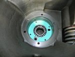
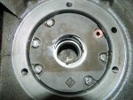
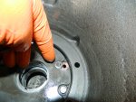
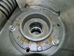
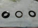
Today I was finishing up the reduction housing.
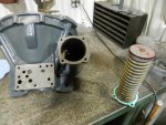
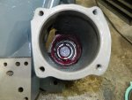
I need to show you a problem the rear pumps have.
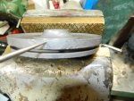
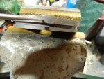
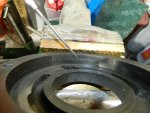
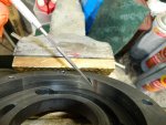
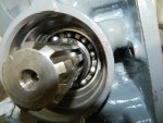
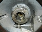
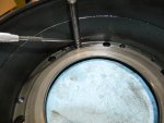
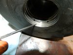
All modern pumps utilize either a "Gear" driven pump, a "Vane" pump, or a "Gerotor" pump. Our 303M transmission uses a Gerotor pump design in the reduction unit. Now a modern Gerotor is a great pump. Up to 98% efficiency, low noise, self-priming, a real good pump. Chrysler used this design for decades in their TorqueFlite transmissions. The problem with the 303M design is the pump is allowed to "Float" the outer ring. The outer ring should be contained in a tight circle. With the outer ring allowed to "flop" around, it creates really weird wear patterns in the pump housing. Areas are "scalloped" out which cause pressure loss. Take a look at these pictures.
002.JPG003.JPG
The "shiny" part is where the outer ring has actually "gouged" out the pump housing. Not good.
Every rear pump I have taken has this problem. It's just a matter of degree.
If I could afford too, I would have a whole new housing made up. One that would contain the outer ring. Since I'm not made of money, I will need to reuse one of these housings. Out of the five housings, I have I picked out the two best for my project. They both still have the "gouges" in the wall, but they are very small.
 
Last edited:

rustystud

Well-known member
9,298
3,077
113
Location
Woodinville, Washington
OK, so here's the nice and pretty pictures of the parts going together.
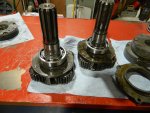
The output shafts have nice new bearings installed on them.
I used "NTN 6210" bearings here.
009.JPG
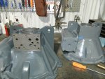
Nice clean housings
011.JPG
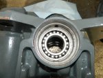
The outer bearing installed with snap-ring in place. I used "NTN 6209" bearings here.
012.JPG
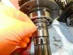
Make sure you put the pump drive key back on the shaft .
014.JPG
New pump gasket installed.
017.JPG
Pump housing installed.
019.JPG
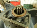
Make sure you install a new "copper" washer shown here. The bolt goes into an oil passage. I also install a stainless steel washer on top of the copper washer so the lock washer does not cut into the copper.
021.JPG
Now install the bearing support.
023.JPG
Now the fun part begins. The output shaft needs to be "pounded" in since the outer bearing has a slight pressure fit.
You must align the keyway with the rear pump drive. You cannot see it going in so be very careful when installing the output shaft,

Success ! The output shaft is in and the snap-ring is installed. I used a full circle ring as they are far stronger than normal snap-rings.
026.JPG028.JPG
I just need to install the oil seal and valve body and the reduction housing is done and ready to go on.
 

Attachments

Last edited:

rustystud

Well-known member
9,298
3,077
113
Location
Woodinville, Washington
I installed the oil seals, but the valve bodies will take a few more days as I need the 9/16" washer that goes on the shift lever. The old ones rotted away, so I ordered stainless steel ones, and stainless roll pins.
I need to make a small "Jib" crane next to my work bench as the 303M is getting very heavy !
So tomorrow I'll be buying some metal up in Everett.
 

rustystud

Well-known member
9,298
3,077
113
Location
Woodinville, Washington
Here's some pictures of the snap-ring and seal install.
001.JPG003.JPG

On the valve body there's really not much to say except the shifter seal install.
There are three parts, one rubber seal and two washers. The washers though are "coned" shaped and need to go on a very specific way. They also are two different sizes internally.
008.JPG You can see that one has a larger internal hole size. That one needs to go against the rubber seal. I've drawn a rather crude picture, but it gives you the general idea.
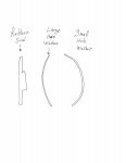
img033.jpg The rubber seal will go in the recess first, then the washers. After that you will install the shifter shaft and then a gasket and then the separator plate.
If you put the washers in the wrong orientation, the rubber seal will not work properly. By having the "coned" washers push against each other they also act as a spring pushing against the rubber seal.
 
Last edited:

DUUANE

Active member
434
189
43
Location
Qualicum Beach BC
If I started to use "sticky" notes, my manual would look like the paper "recycle bin" !

Side note here. Are you still active duty ?
I was in the Marines from late 1981 to 1987 .
M60A1 Rise Passive, Oh-Ra !!!!
Nope. Missunderstanding. My fault for using a capital M.
Marine as in sub-sea OEM tech manuals when they will supply any. Most times i have to work by x-ray vision as the drawings are proprietary intellectual property of the manufacturer. There have been times where we had OEM reps from europe and the US at the same time, and the euro's wouldnt share drawings with their own guys from north america. Head office says 🖕

Crazy stuff.
 
Top
AdBlock Detected

We get it, advertisements are annoying!

Sure, ad-blocking software does a great job at blocking ads, but it also blocks useful features of our website like our supporting vendors. Their ads help keep Steel Soldiers going. Please consider disabling your ad blockers for the site. Thanks!

I've Disabled AdBlock
No Thanks