• Steel Soldiers now has a few new forums, read more about it at: New Munitions Forums!

  • Microsoft MSN, Live, Hotmail, Outlook email users may not be receiving emails. We are working to resolve this issue. Please add support@steelsoldiers.com to your trusted contacts.

Circuit Help Needed...

Artisan

Well-known member
2,761
227
63
Location
CDA Idaho
Can anyone help me drawing a circuit? I want to use an M939 Heater switch (or a like switch w/ same dimensional characteristics) to power HIGH and LOW beams on a pair of Armored Lights. Below are the lights and switch. The bulb inside is a GE4811. CLICK HERE for a partial schematic. I believe this switch was originally set up so it would send 12V to the heater blower motor for low, and 24V for high. Is it possible to do what I want to do w/ this switch? I have a panel made for these types of switches.? If anyone can draw me a safe, clear circuit I would be happy to send lunch money, w/ a few beer dabloons as well! I believe I see how to do this using 2 switchs, by switching on switch #1 and then switch on switch #2 but I need to try to do this w/ one switch.
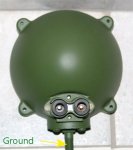
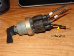
irlight.jpg irlight-switch.jpg
 

quickfarms

Well-known member
3,495
25
48
Location
Orange Junction, CA
The speed on a blower motor is usually controlled by a resistor that is in the air flow, to keep it cool.

The switch looks like a common rotary switch.

You need a ohm meter, this is part if a multimeter,

With the switch in the off position there should be no conductivity between the wires.

With the switch in the first position the should be conductivity between two wires, write the numbers down.

Repeat the last step for the second position.

The number that is in each list is the common wire or hot. The other number is the wire that is controlled by each position.

The next issue is weather the switch can handle the amps without a relay. It probably can, due to the fact that it is a blower motor switch, but if the switch gets hot you will need to add relays.
 

Artisan

Well-known member
2,761
227
63
Location
CDA Idaho
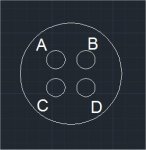
This drawing is a picture of the back of the switch. A&B=Low*------------A&C=High* (*that could be switched, no biggie at this point) I cannot pair D to Anything! It is dead. I looked for continuity and it is dead. This hole (D) comes OE w/ a plug in it.

irlight-switch2.jpg
 
Last edited:

steelandcanvas

Well-known member
6,187
85
48
Location
Southwestern Idaho
This drawing is a picture of the back of the switch. A&B=Low*------------A&C=High* (*that could be switched, no biggie at this point) I cannot pair D to Anything! It is dead. I looked for continuity and it is dead. This hole (D) comes OE w/ a plug in it.
The switch is a Single Pole Double Throw (SPDT). The "D" connection is not needed/used in this switch configuration. The "D" connection would be used for a Double Pole, Single Throw (DPDT), which would be used to control 2 separate circuits. The SPDT switch is the correct switch for your heater if it has a "center off" position. This is the same switch I use on the heater circuit in my Deuce, the current draw is not enough to require a relay.
 
Last edited:

Artisan

Well-known member
2,761
227
63
Location
CDA Idaho
The switch is a Single Pole Double Throw (SPDT). The "D" connection is not needed/used in this switch configuration. The "D" connection would be used for a Double Pole, Single Throw (DPDT), which would be used to control 2 separate circuits. The SPDT switch is the correct switch for your heater if it has a "center off" position. This is the same switch I use on the heater circuit in my Deuce, the current draw is not enough to require a relay.
Indeed, for a heater it is correct, my question is can I use that same switch to power 2- of the lights I have pictured, so when on LOW I get low beams and when on HIGH I get high beams .
 

steelandcanvas

Well-known member
6,187
85
48
Location
Southwestern Idaho
Yes, it will work for your lighting application. I just re-read your post and I must have had heater switch on the brain. The switch is probably rated at 20 Amps. Your 4811's draw 4 Amps a piece on high beam, and 2 Amps a piece on low beam. 110W/28V=3.92A, 55W/28V=1.96A. I see no reason to use a relay as the current draw is well within the switch's capacity. I also used this same style Mil-Spec switch to control my back-up lights, and the same lights, although I just used the high beam filaments.
 
Last edited:

Artisan

Well-known member
2,761
227
63
Location
CDA Idaho
Can you draw me the circuit? That is the whole deal...I need someone to draw me the circuit using the heater switch.
 

Artisan

Well-known member
2,761
227
63
Location
CDA Idaho
put the 24 0r 12 volt power in on pin A-- that is the common pin. put the low beam out on b and the high beam out on c. A&B=low A&C= high
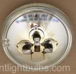
Hmmm, well, I though both circuits had to be hot at the same time to make high beam? Here is the bulb online, showing a pic of the back of the bulb. 55W or 110W's , so that is what makes me believe I need to heat up both circuits at one time to get HIGH.
 

steelandcanvas

Well-known member
6,187
85
48
Location
Southwestern Idaho
Hmmm, well, I though both circuits had to be hot at the same time to make high beam? Here is the bulb online, showing a pic of the back of the bulb. 55W or 110W's , so that is what makes me believe I need to heat up both circuits at one time to get HIGH.
No, there are 2 separate filaments inside the lamp, one connection is low beam and the other connection is high beam, make sure you have a good ground on the mounting stud.
 

Artisan

Well-known member
2,761
227
63
Location
CDA Idaho
Well, I just heated up the left side then the right side and the "brightness" is the same. I need to find out what vehicle these things came on originally and look at the wiring schematic. If it only shows a DIMMER switch next I need to determine if indeed dimmer switches just heat up one side for low and both together for high.
 

steelandcanvas

Well-known member
6,187
85
48
Location
Southwestern Idaho
Do you have an Ohm Meter? If so, check one connection to ground, then check the other connection to ground. If the Ohm reading is the same for both filaments, then both need to be on for "high beam". If you get about 14 ohms, that's the low beam (55W). If you get 7 ohms, that's the high beam (110W). When I installed my lights I thought they had 2 intensities, I chose the higher of the two. I might learn something here about my own lights, depending on what you come up with. If you don't have an Ohm meter, I can check the resistance check later today.
 

Artisan

Well-known member
2,761
227
63
Location
CDA Idaho
I failed electrical school, having said that, if I grab a multi-meter and turn it to the "200" (the lowest) setting in the OHMS section (the horseshoe area) and if I check both left and right connections to the ground which is the mounting stud, I get almost the same reading on both, 2.9 and 2.8 . So I assume now that to get high beam BOTH get heated at the same time. Back to square one, is there any voodoo wiring a guy can do to use a two position heater switch to get low and high beams for these lights. (PS, I guess I will rig up a way to heat up both at the same time now and see if she blows or goes! )
 

Artisan

Well-known member
2,761
227
63
Location
CDA Idaho
OK I just heated up both at the same time and I get a MUCH brighter light, while it was on I unplugged one at a time and got what I might call a high and a low beam. The intensity of the beam was hot a few inches away but heck, my headlights throw heat darn near 3 feet away. Maybe I will write GE and ask them.
 

steelandcanvas

Well-known member
6,187
85
48
Location
Southwestern Idaho
I just went out to the shop and measured the resistance between one terminal and ground and the other and ground. I got 7 Ohms on one and 14 ohms on the other. When you do the calculation, like I did above, it comes out to 110W and 55W respectively. However, I have not removed the lamp from the fixture to verify it is a 4811.
 

Sambor

New member
39
0
0
Location
Weatherford, Texas
I think that one of the terminals on the light is a common ground for both filaments. Otherwise how would the light ground itself? If you use your meter, put one lead in the center pin of the headlight connector and the other lead to ground-- you should have almost zero resistance. If you measure from one pin of the headlight to the center it will give you the resistance for that filament. The switch you have uses 24 volts to pin A all the time-- it is looking for you to either connect that to pin B OR pin C. So, if you have 24 volts on pin A and you turn the switch so A&B are connected-- the 24 volts goes out on Pin B to whatever you have connected to it. Same applies to pin C. I can't remember ever seeing a headlamp that both filaments light up at the same time but there may be some. I just got finished wiring my old 46 Dodge truck and it uses a dual filament lamp-- one for low and one for high-- and not together.
 

Artisan

Well-known member
2,761
227
63
Location
CDA Idaho
No. The mounting stud is the ground for sure. If you look at the bulb you will see 3 contacts, the middle is the ground and inside the light there is a wire from the middle contact to the stud.
 

Artisan

Well-known member
2,761
227
63
Location
CDA Idaho
I guess if I could find a vehicle these lights came installed on stock, I might be able to dig up a TM w/ a wiring schematic. It's looking like I might just use a standard battery switch and wire it to a floor dimmer switch.
 
Top
AdBlock Detected

We get it, advertisements are annoying!

Sure, ad-blocking software does a great job at blocking ads, but it also blocks useful features of our website like our supporting vendors. Their ads help keep Steel Soldiers going. Please consider disabling your ad blockers for the site. Thanks!

I've Disabled AdBlock
No Thanks