• Steel Soldiers now has a few new forums, read more about it at: New Munitions Forums!

  • Microsoft MSN, Live, Hotmail, Outlook email users may not be receiving emails. We are working to resolve this issue. Please add support@steelsoldiers.com to your trusted contacts.

CTIS and Arduino

Ronmar

Well-known member
3,829
7,436
113
Location
Port angeles wa
So you are using the wet tank pressure switches 115 PSI closed to 90 PSI open points to control the inflate timing? I thought about using that switch to control an indicator light on my manual panel to indicate wet tank pressure, but I find I can do it prettywell by ear. Dryer purge = full, inflate for a few seconds then pause till I hear the purge. I havnt timed it, but filling in similar pulses by hand, I am pretty sure it does not take 30 minutes to go from 20 to 80 PSI. I will time it, but 30 minutes sounds like an awfully long time for something bad to happen. If it is inflating in pulses, it should return comparable steps in pressure that could be checked as an expected result.

I would suggest something in the code to cope with leaks, like an expected pressure reading witin a certain range when you check pressure initially.

You could also read the pressure 3-4 times over a few seconds after opening the wheel valves, looking for a change in the reading. If you have one tire that is leaking, as soon as you close control and send a shot of air to open the wheel valves, the pressure measurement at the PCU will be unstable as the tire pressures equalize amongst themselves. Have seen this watching the pressure gauge connected to the PCU before I fixed a leaking wheel valve. That took care of most of the change, but I was still seeing a change in pressure after opening the valves which led me to a leak at the T fitting down by the transmission. So reading out of range(unable to open wheel valves?) or unstable indicates a leak...
 
Last edited:

m-35tom

Well-known member
Supporting Vendor
3,021
222
63
Location
eldersburg maryland
Remember inflating at engine idle speed is much different than at 1500 rpm or more. At a higher rpm the wet tank switch does not cycle.
 

Plasa

Well-known member
Steel Soldiers Supporter
256
322
63
Location
Italy
Hello Ronmar.
No, I don't use the wet tank switch for inflation time. Only for starting the system. Here are the steps:

- open control valve
- after 3 seconds: open inflate valve
- after 3 seconds: close inflate valve
- after 30 seconds: check pressure
- if too low: inflate:
-- open inflate valve
-- after 30 seconds: close inflate valve
-- after 5 seconds: check pressure, if too low, continue inflate, otherwise:
-- close all valves
-- after 30 seconds: open control, after 3 seconds inflate valve, after 3 seconds close inflate valve wait 30 seconds, read pressure
- if too high: deflate
-- open deflate valve
-- after 15 seconds close deflate valve
-- after 2 seconds open inflate valve, after 2 seconds close inflate valve, wait 10 seconds, read pressure. then same as inflate...

The idea for air leaks is good, I will include something to check pressure for 5 seconds, if changes there is a leak. Maybe on every initial pressure check...

Thank you Ronmar!

Christian

So you are using the wet tank pressure switches 115 PSI closed to 90 PSI open points to control the inflate timing? I thought about using that light to control an indicator light on my manual panel to indicate wet tank pressure, but I find I can do it prettywell by ear. Dryer purge = full, inflate for a few seconds then pause till I hear the purge. I havnt timed it, but filling in similar pulses by hand, I am pretty sure it does not take 30 minutes to go from 20 to 80 PSI. I will time it, but 30 minutes sounds like an awfully long time for something bad to happen. If it is inflating in pulses, it should return comparable steps in pressure that could be checked as an expected result.

I would suggest something in the code to cope with leaks, like an expected pressure reading witin a certain range when you check pressure initially.

You could also read the pressure 3-4 times over a few seconds after opening the wheel valves, looking for a change in the reading. If you have one tire that is leaking, as soon as you close control and send a shot of air to open the wheel valves, the pressure measurement at the PCU will be unstable as the tire pressures equalize amongst themselves. Have seen this watching the pressure gauge connected to the PCU before I fixed a leaking wheel valve. That took care of most of the change, but I was still seeing a change in pressure after opening the valves which led me to a leak at the T fitting down by the transmission. So reading out of range(unable to open wheel valves?) or unstable indicates a leak...
 

coachgeo

Well-known member
5,143
3,461
113
Location
North of Cincy OH
If Im not mistaken the 939 trucks had 80psi controllers also..... AND different wheel valves to match... not sure about valves in between. Something to consider if you up the pressures. Something to look into maybe is... did the wheel valves and other valves part #'s on the MTV's that had higher pressure controllers have the same part #'s for all the other valves that the LMTV did... or were they different? If different.... why? Maybe they were mean to match the higher pressure demands?
 

Plasa

Well-known member
Steel Soldiers Supporter
256
322
63
Location
Italy
Yes, quite sure that there are diffrent wheel valves, transducer and ECU. I have a ECU with highway pressure about 95psi on a M1078, perhaps it's a 80psi ECU for a 939 or M1089 truck. With that ECU my CTIS was not able to get highway pressure and tires went overinflated...

Christian

If Im not mistaken the 939 trucks had 80psi controllers also..... AND different wheel valves to match... not sure about valves in between. Something to consider if you up the pressures. Something to look into maybe is... did the wheel valves and other valves part #'s on the MTV's that had higher pressure controllers have the same part #'s for all the other valves that the LMTV did... or were they different? If different.... why? Maybe they were mean to match the higher pressure demands?
 

Ronmar

Well-known member
3,829
7,436
113
Location
Port angeles wa
Tom my switch still cycles at high RPM untill the tire pressure reaches somewhere over 65PSI. At that point the wet tank outflow to CTIS decreases closer toward what the inflow from the compressor is. At 40 PSI in the tires, I can go from a full wet tank to the 90PSI wet tank switch opening with a 4 second shot of CTIS inflate. It is only around 5 seconds to drop the tank to the 90PSI switch point at full RPM...

IMO I think there is a reason they chose a wet tank switch with those closed and open contact actuations. I think there are some advantages to using that wet tank switch to control the fill. If you just turn the control and inflate valves on at low RPM or low tire pressures, the tank will quickly empty to the point where the rubber diaphram and spring in the protection valve start regulating the flow as the tank hovers around the 85PSI protection valve setpoint. Having watched this on a pressure gauge at the PCU, the gauge needle starts to flutter as the tank empties. Not sure what effect this will have on the protection valve long term. At higher RPM and pressures it would allow you to maintain longer duration fill pulses. I suspect the CTIS designers used a combination of this switch and a max inflate pulse duration, to insure the tank fills full periodically to maintain brake pressures.

Christian: If I can make some suggestions, you can shorten some of your times. It dosnt take a 3 second shot of air to open the wheel valves and you should be able to check tire pressure immediatly after the fill valve closes. At low pressures, a 3 second shot of air is the entire volume of the wet tank:)

I would suggest you use the wet tank switch to control the inflation cycles which will keep the tank pressure cycling between 115PSI and 90 PSI and would automatically accomidate different outflow rates with differing pressure and differing supply flow due to engine RPM while keeping air peaks in there to maintain brake supply.

I wanted to fix a leak so after that I timed a deflate and a fill on my manual system. It took about 4 minutes to deflate from 60 to 20PSI checking pressure every 60 seconds. To inflate, It took 9 minutes from 20 to 40, another 9 minutes from 40 to 60 and 11 additional minutes from 60 to 80PSI with the engine at idle. I filled in 3-4 second shots of inflate, with 9 seconds of recovery time between each shot. As the tires fill above 60PSI I can increase the inflate durations as the outflow to the tires slows, but it still takes about 9-10 seconds for the tank to recover to 120PSI. Tank recovery is a lot faster at higher RPM
 
Last edited:

coachgeo

Well-known member
5,143
3,461
113
Location
North of Cincy OH
Yes, quite sure that there are diffrent wheel valves, transducer and ECU. I have a ECU with highway pressure about 95psi on a M1078, perhaps it's a 80psi ECU for a 939 or M1089 truck. With that ECU my CTIS was not able to get highway pressure and tires went overinflated...Christian
Others have swapped the ecu only and had no problems... it just ran highway at higher pressure. Last conversation on your truck seemed to be left that alot was changed on your truck so its hard to measure from it..
 

Plasa

Well-known member
Steel Soldiers Supporter
256
322
63
Location
Italy
On my truck only the ECU was changed, for sure. All the rest is original and never touched. But anyway, now with the new self made ECU works, and that is the most important thing...

Thanks and regards from Italy!

Christian
Others have swapped the ecu only and had no problems... it just ran highway at higher pressure. Last conversation on your truck seemed to be left that alot was changed on your truck so its hard to measure from it..
 

Plasa

Well-known member
Steel Soldiers Supporter
256
322
63
Location
Italy
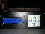
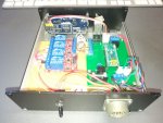
Hello Forum. Time is running and project is going on. I finish the configuration mode that enable (when you short a contact inside) to manually inflate / deflate the tires and to save the actual pressure as new default pressure for the 4 diffrent modes. I also add a switch to cutoff the power in chase of emergency/malfuncion.
The P<> is a error message that something is wrong with the pressure transducer: ambient pressure is out of range...
For information, the original pressure transducer should be a 100psi transducer (a map(0,1023,0,103) conversion) shows the right pressure. In the next 3 weeks I am travelling through Europe, testing also the software. When it is usable and reliable I will put the sources on github.

IMG_20190214_110656.jpgIMG_20190214_102005.jpg

Christian
 

Fatalid

Member
Steel Soldiers Supporter
123
11
18
Location
Mesa, AZ
Stuff like this is super awesome! I live and breath tinkering with electronics.... my desk at work is littered with arduino boards, bread boards, relays, all sorts of components, solder station, etc. etc. etc.

I love seeing this kind of stuff take life.

Good Work!
 

Plasa

Well-known member
Steel Soldiers Supporter
256
322
63
Location
Italy
For everyone that want build a new CTIS ECU:
Don't forget flyback diodes, it drove me crazy trying out why sometimes the Arduino reset without any reason when shutting off the valves... Seems that no diodes are in the solenoids...

Happy hacking!

Christian
 

Plasa

Well-known member
Steel Soldiers Supporter
256
322
63
Location
Italy
Hello all.
Sorry for the late answer, but due heavy work I did not found the time to answer.

After 2000 miles I must admit that the Arduino and CTIS do a great job. It works like a sharm, every 15 minutes checks the pressure and adjust it. No problems after all. More problems with broken coolant houses... But that's another thread :)

What I add is a config switch to set the 4 default pressures, and can be used as a manual emergency function. In config mode no check is done, as long you press inflate / deflate button the system inflate / deflate.

And a power off switch to cut off completely shot off the CTIS, if something go wrong and/or no need if continues checks.

The total cost of the ECU on Arduino is about 100$, including connector, arduino, alu housing, relays etc. I sold 2 ECU's to the company who sold me the truck, because it works with every type of pressure transducer and type of truck. Installation is easy, just plug off the old ECU and plug in the new one, set up the 4 pressures you like and done...

If someone is interested in the arduino sketch, or has an idea how to make it public available, or want to build it for selling, drop me a message, I will share all information with you! I have some problems getting spare parts of this awesome truck's here in Europe, so maybe there's someone in the US who can help me finding some spare part, or a civilian part number...

Christian
 
Top
AdBlock Detected

We get it, advertisements are annoying!

Sure, ad-blocking software does a great job at blocking ads, but it also blocks useful features of our website like our supporting vendors. Their ads help keep Steel Soldiers going. Please consider disabling your ad blockers for the site. Thanks!

I've Disabled AdBlock
No Thanks