• Steel Soldiers now has a few new forums, read more about it at: New Munitions Forums!

  • Microsoft MSN, Live, Hotmail, Outlook email users may not be receiving emails. We are working to resolve this issue. Please add support@steelsoldiers.com to your trusted contacts.

CTIS troubleshooting - Bad ECU?

ckouba

Well-known member
Steel Soldiers Supporter
615
1,752
93
Location
Oregon
Hey gang,

I've gone dark here a bit lately with a few other projects getting priority, but thanks to @Lostchain, I recently took a run at troubleshooting the CTIS issue I had in the fall. For those late to the party, I documented it here:


Long story short, we found a very obvious leak where the RT front line was disconnected from the valve. Ever so optimistically, I started up the system again and it still didn't work. It was cycling a solenoid at about 2Hz. We went through the entire Dana procedure, checking solenoid resistances, continuities, etc... and got to the end of the troubleshooting procedure which basically said I need to replace the ECU. The codes on the Dana system were 34, 35, and 54. We fixed the 26- massive leak in system.

  • Code 34:

    NO PCU SENSOR READING (System non-operative): No sensor voltage to ECU. Clears 5 seconds following a valid reading. 1) Sensor is electrically disconnected 2) Pressure signal wire (XDCR SIGNAL) is shorted to ground, or open 3) PCU sensor VREF wire is shorted to ground, or open 4) Faulty sensor PCU SENSOR READING TOO HIGH (System non-operative): Sensor voltage higher than allowed. Clears 5 seconds following a valid reading. 1) Pressure signal wire (XDCR SIGNAL) is shorted to power or XDCR VREF 2) Faulty sensor

  • Code 35:
    OUT OF RANGE ATMOSPHERIC READING (System waits to check pressures): Atmospheric pressure check indicates vented PCU pressure is outside of valid atmospheric range (5-20 psia). Repair and request pressure check to clear (press any mode button or run flat). 1) Poor ground connection to PCU sensor 2) Faulty PCU sensor (ex, frozen water contamination) 3) Faulty PCU or blocked PCU exhaust vent

  • Code 54:
    ELECTRICAL SOLENOID FAILURE (System non-operative): Solenoid fails electrical diagnostics for approximately 2 seconds. Repair & cycle ignition to clear. 1) Solenoid or harness wire is shorted to ground 2) Solenoid or harness wire is shorted to power 3) Faulty solenoid


As part of our non-TM troubleshooting, we checked the pressure switch at the wet tank and couldn't get a reading on it from the plug. Even with it unplugged though, the system tried to work- it was cycling the solenoid. As we understand it, without a signal (closed switch) from the pressure tank, the system shouldn't be doing anything.

If the ECU is trying to run the system with an open circuit from the pressure switch, is that indicative of a bad ECU? That is about the only thing that might make sense out of this to me.

Does any of this make sense to anyone? Is there something we missed in the troubleshooting? Any recommendations? Anybody have a spare ECU (2000 M1088A1)?

Thanks in advance,
Chris
 

Ronmar

Well-known member
3,900
7,567
113
Location
Port angeles wa
What do the primary and secondary brake gauges read when the dryer purges? It should be 125PSI, and the wet tank switch should close above 117… you should be able to measure this closure between two of the 3 pins on the pressure switch connector.

Two of those codes you listed indicate a bad pressure sensor on the pressure control unit and a solenoid circuit open or shorted on one of the PCU solenoids. I suspect all of those codes could be caused by a bad wiring or connection between the controller and the PCU… The pulsing solenoid indicates to me a possible weak connection. When energized, the coil starts to pull in, but as it draws current the weak connection resists current flow causing a voltage drop that releases the solenoid, which causes a voltage increase that re-energizes the solenoid.. This cycle will repeat until power is removed. This could be between controller and PCU, or even power feeding the controller… a bad connection in the solenoid coil can also do this.

You can manually control the PCU from the controller connector with a pair of jumper wires. This will at least test the coils and wiring and solenoid function in the PCU. You can use any small wire, the conductors out of phone or Cat-5 cable work good. Cut two of them about 3-4” long, strip the ends and twist one end of each jumper together to form a V. You will also want to run the truck for a bit to fill the air tanks before shutting the truck down for the test, or connect the truck air system to shop air.

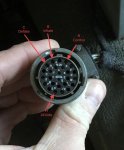
With the controller connector in your hand place the twisted end(point of the V) into socket H(24V) on the connector, and put the other end of one of the jumpers into socket R(control solenoid). When you turn on the main switch you should hear the control solenoid close. This should seal the system. Now BRIEFLY insert the end of the other jumper into socket B(about 1 second) to apply 24V to the supply solenoid to give a shot of air from the wet tank. This should pressurize the system and open the wheel valves. Now you can really look for leaks as the system should be able to set like this as long as the main switch is on. You can do this control and brief inflate sequence 3-4 times with a full wet tank. A full on inflate will deplete the wet tank in about 3-4 seconds.

You can use the same jumper you used to trigger supply/inflate to trigger the deflate solenoid by connecting its free end to socket C(deflate solenoid). This will cause air to escape thru the little regulator valve on the PCU and the front and rear dump valves should open and start dumping air. To stop the dump, remove the jumper and give it a little shot of air to bring the system pressure up to tire pressure which should close the dump valves.

if it starts doing anything weird, simply turn off the main switch to remove CTIS power from the connector/socket H, or pull the H-R jumper… i have a youtube video under username rronmar that shows manual control of the PCU using pushbuttons to make the connections described above…

This of course will not test the pressure sensor on the PCU, but you should at least be able to ring out the wires from the controller connector to the pressure sensor on the PCU…

They also incorrectly oriented that pressure sensor with the fitting pointing straight up. Any crap in the system will collect in the sensor pressure port…


F0D41E6F-367F-423E-ABE6-4D800F0D066B.jpeg
 

Lostchain

Well-known member
Steel Soldiers Supporter
285
589
93
Location
Portland, OR
An additional thing to add. When we connected with the Dana diagnostic tool the unit would stop the cycling, and we were able to get it to inflate and deflate. This makes me think the solenoids are good(and they ohmed out good) However what was very strange was that as soon as the system was inflating, the pressure switch would change status to “open”. As soon as you stopped and vented the system, the pressure switch would return to closed. It behaved this way whether the pressure switch was plugged in or not.

In my mind, this is the strangest component because the system shouldn’t be doing anything at all with an open pressure switch. And it certainly shouldn’t be reporting it closed when it is unplugged.
 

Ronmar

Well-known member
3,900
7,567
113
Location
Port angeles wa
An additional thing to add. When we connected with the Dana diagnostic tool the unit would stop the cycling, and we were able to get it to inflate and deflate. This makes me think the solenoids are good(and they ohmed out good) However what was very strange was that as soon as the system was inflating, the pressure switch would change status to “open”. As soon as you stopped and vented the system, the pressure switch would return to closed. It behaved this way whether the pressure switch was plugged in or not.

In my mind, this is the strangest component because the system shouldn’t be doing anything at all with an open pressure switch. And it certainly shouldn’t be reporting it closed when it is unplugged.
Thats weird. Just to clarify, pressure switch(wet tank) or pressure sensor(on PCU)?

If the switch circuit was shorted somewhere along the path from controller connector to wet tank. That would lie to the controller and it would allow it to try and function. The wet tank switch tells the controller when the wet tank is full(closes above 117 PSI) then it stays closed as the wet tank drains until the wet tank has nothing left to give and opens the sw below 89PSI. It stays open until the pressure once again exceeds 117PSI. It has 3 pins in the sw connector, so you need to look at the correct pair, and you need to be able to control air pressure from below 89 to above 117 in the wet tank. This is easiest with an external air source and a regulator, either attached directly to the wet tank, or remove the switch and screw it directly into the regulator(with a gauge) output port. Then you can cycle the pressure applied to the sw with the regulator knob to see where it changes state.

With the above codes for the PCU air pressure transducer, I am also surprised it is doing anything. It only has one sensor, it is pretty important that it be valid. It does a check see if it can see atmospheric pressure. It is a 0-5v@100 PSI sensor. so from its 5V input, it is expecting to see a return for atmospheric pressure Before it seals and pressurizes the system.

If it stopped cycling and you could control the solenoids using the scan tool, then that indicates to me an internal processor/controller issue. I suspect the scan tool would bypass the control routine and take control of the solenoid power circuits directly when manually testing… And since that worked, the PCU is probably OK. But it is also hard to determine how the switch and pressure transducer anomalies would effect it. Garbage in-garbage out…
 

Lostchain

Well-known member
Steel Soldiers Supporter
285
589
93
Location
Portland, OR
Thats weird. Just to clarify, pressure switch(wet tank) or pressure sensor(on PCU)?
The pressure switch on the wet tank. Even when unplugged, the ECU reported its status as closed.


If it stopped cycling and you could control the solenoids using the scan tool, then that indicates to me an internal processor/controller issue. I suspect the scan tool would bypass the control routine and take control of the solenoid power circuits directly when manually testing… And since that worked, the PCU is probably OK.
This is my thought as well. Any time the system was trying to inflate, the Pressure switch would suddenly report "OPEN" to the ECU and would remain that way till we canceled the test. So what it seemed like to me, is that under normal control routines, the system would charge the lines, instantly see the pressure switch "OPEN" signal and then dump/vent the system to wait for more air, but then as soon as it dumped, it would get a CLOSED signal again and repeat the cycle of trying to check the pressures again, thus the rapid cycling effect we were observing. The Dana software in test mode bypasses the control routines, but it does warn you that the pressure switch is "OPEN" while inflating, even though it prevents that signal from overriding what you are currently commanding the system to do.
 

coachgeo

Well-known member
5,150
3,466
113
Location
North of Cincy OH
could something be wired wrong..... pin placed in wrong hole? Or some how you have some power hitting your ground somewhere...... thus back feeding or confusing the switch?
 

Ronmar

Well-known member
3,900
7,567
113
Location
Port angeles wa
but it continues to short cycle with the switch unplugged? Either the switch sense circuit is not working(bad controller) or perhaps there is a low resistance path in the wiring back to the switch…

The tester gives you switch state to see if it is cycling properly with manual operation and compressor cycling... I would suspect it probably can also read PCU pressure transducer output…
 

Lostchain

Well-known member
Steel Soldiers Supporter
285
589
93
Location
Portland, OR
but it continues to short cycle with the switch unplugged? Either the switch sense circuit is not working(bad controller) or perhaps there is a low resistance path in the wiring back to the switch…
Yes, switch being unplugged make no difference to the behavior.


The tester gives you switch state to see if it is cycling properly with manual operation and compressor cycling... I would suspect it probably can also read PCU pressure transducer output…
To clarify what I mentioned in my previous post, the Test Tool reports the switch as closed at any and all times the system is at rest, whether the switch is plugged in or not. The instant the system tries to operate in any function, the ECU immediately sees that the switch is "OPEN" again irrespective of whether the switch is actually plugged in or not. In manual diagnostic testing mode, while inflating, deflating, or checking, that switch is still reported as "OPEN" however the PCU appears to behave properly, and you get readings that appear correct from the PCU pressure transducer. For example, it was reporting somewhere in the neighborhood of 40ish PSI which I thought was wrong, but then we actually checked the tires and sure enough, all that short-cycling and testing had actually drawn all 6 tires down to 40psi.
 

Ronmar

Well-known member
3,900
7,567
113
Location
Port angeles wa
I would think it is supposed to accurately reflect switch state, so either the controller is mis-reading the switch circuit or there is a problem with the switch circuit causing it.

I would ring out that circuit really well. An ohm meter will tell you if you have a good circuit by jumpering one end and measuring resistance between the conductors at the other end. The ohm meter won’t tell you if you have any leakage between the conductors though.

Disconnect the circuit at both ends(controller and wet tank switch), put voltage on one lead to the switch and see if there is any leakage across to the other lead by measuring for voltage on the other lead. Repeat this test for both conductors in the switch circuit.
 

Lostchain

Well-known member
Steel Soldiers Supporter
285
589
93
Location
Portland, OR
I would think it is supposed to accurately reflect switch state, so either the controller is mis-reading the switch circuit or there is a problem with the switch circuit causing it.
Agreed, on a working truck (mine) the ECU switch status always reflects the physical status of the switch no matter what operating mode.


I would ring out that circuit really well. An ohm meter will tell you if you have a good circuit by jumpering one end and measuring resistance between the conductors at the other end. The ohm meter won’t tell you if you have any leakage between the conductors though.

Disconnect the circuit at both ends(controller and wet tank switch), put voltage on one lead to the switch and see if there is any leakage across to the other lead by measuring for voltage on the other lead. Repeat this test for both conductors in the switch circuit.
@ckouba In addition to what @Ronmar suggests above, From the Dana Manual troubleshooting a Pressure Sensor code 31 (which I know we didn't have but the circuit is definitely misbehaving) you should ohm out both wires at the switch connector at the wet tank to ground. Basically if the wiring is completely tested clean every way from Sunday and the ECU is still reading "closed" at an inappropriate time, the ECU should be swapped and the system re-checked. Both this code and the PCU Supply solenoid code troubleshooting steps all dead end at the same thing, bad ECU. I feel pretty good about the testing we did on the PCU side. We didn't ohm out the pressure switch side, you should do that and if clean, next steps gotta be swap the ECU. You mentioned that this happened when they removed the habitat, maybe the wiring in the neighborhood of the wet tank got crushed.. Ohm test should let you know. Also, double check that ground strap at the CTIS controller as I thought you mentioned that looked like it wasnt stock.


Capture.JPG
 
Last edited:

ckouba

Well-known member
Steel Soldiers Supporter
615
1,752
93
Location
Oregon
Holy crap.... Everyone else is doing my homework for me! Thanks gents.

Brandon is spot on with all his updates of what we did, and reading through, I think he answered all the questions (probably better than I could've). Truth be told, he did the heavy lifting Weds. I am still a bit buried with other responsibilities but will try to get at this shortly.

Thanks for all the feedback and brain calories burnt on my issue.

Chris
 

MAYHEM_SOLUTIONS287

New member
2
1
1
Location
Arizona
What do the primary and secondary brake gauges read when the dryer purges? It should be 125PSI, and the wet tank switch should close above 117… you should be able to measure this closure between two of the 3 pins on the pressure switch connector.

Two of those codes you listed indicate a bad pressure sensor on the pressure control unit and a solenoid circuit open or shorted on one of the PCU solenoids. I suspect all of those codes could be caused by a bad wiring or connection between the controller and the PCU… The pulsing solenoid indicates to me a possible weak connection. When energized, the coil starts to pull in, but as it draws current the weak connection resists current flow causing a voltage drop that releases the solenoid, which causes a voltage increase that re-energizes the solenoid.. This cycle will repeat until power is removed. This could be between controller and PCU, or even power feeding the controller… a bad connection in the solenoid coil can also do this.

You can manually control the PCU from the controller connector with a pair of jumper wires. This will at least test the coils and wiring and solenoid function in the PCU. You can use any small wire, the conductors out of phone or Cat-5 cable work good. Cut two of them about 3-4” long, strip the ends and twist one end of each jumper together to form a V. You will also want to run the truck for a bit to fill the air tanks before shutting the truck down for the test, or connect the truck air system to shop air.

With the controller connector in your hand place the twisted end(point of the V) into socket H(24V) on the connector, and put the other end of one of the jumpers into socket R(control solenoid). When you turn on the main switch you should hear the control solenoid close. This should seal the system. Now BRIEFLY insert the end of the other jumper into socket B(about 1 second) to apply 24V to the supply solenoid to give a shot of air from the wet tank. This should pressurize the system and open the wheel valves. Now you can really look for leaks as the system should be able to set like this as long as the main switch is on. You can do this control and brief inflate sequence 3-4 times with a full wet tank. A full on inflate will deplete the wet tank in about 3-4 seconds.

You can use the same jumper you used to trigger supply/inflate to trigger the deflate solenoid by connecting its free end to socket C(deflate solenoid). This will cause air to escape thru the little regulator valve on the PCU and the front and rear dump valves should open and start dumping air. To stop the dump, remove the jumper and give it a little shot of air to bring the system pressure up to tire pressure which should close the dump valves.

if it starts doing anything weird, simply turn off the main switch to remove CTIS power from the connector/socket H, or pull the H-R jumper… i have a youtube video under username rronmar that shows manual control of the PCU using pushbuttons to make the connections described above…

This of course will not test the pressure sensor on the PCU, but you should at least be able to ring out the wires from the controller connector to the pressure sensor on the PCU…

They also incorrectly oriented that pressure sensor with the fitting pointing straight up. Any crap in the system will collect in the sensor pressure port…


View attachment 869020
Hey anyone know what's up with the ctis when all lights are on? All red lights are on when I select a function like freeway I get no response light just stay on.
 

Ronmar

Well-known member
3,900
7,567
113
Location
Port angeles wa
5 solids? Internal fault, it’s now an interesting coffee table conversation starter, as it is a little bulky to try and skip across a lake… Mine was that way when I got my truck, prime motivator for my going manual…
 

MAYHEM_SOLUTIONS287

New member
2
1
1
Location
Arizona
5 solids? Internal fault, it’s now an interesting coffee table conversation starter, as it is a little bulky to try and skip across a lake… Mine was that way when I got my truck, prime motivator for my going manual…
That's unfortunate. I thought it be jacked up. Thanks brother. What do you mean by going manual?
 

walshjuice

New member
11
1
3
Location
Vail, CO
I’ve got the same issue that just started. All 5 lights are illuminated. They are dimmer than normal when just a single is illuminated. No flashing. The system was working flawlessly previously. On my last trip it randomly went to a normal single light while on the highway. Then it went back to 5 steady dimmed lights. Any thoughts?
 

Ronmar

Well-known member
3,900
7,567
113
Location
Port angeles wa
That's unfortunate. I thought it be jacked up. Thanks brother. What do you mean by going manual?
I did 2 videos, this link is to The latest version, watch both of them. Tgere is a link in the description of the first vid to the first wiring diagram. I have not done a diagram for my latest version(added a latching circuit to the control relay).

The system is not particularly complicated, the controller manipulates 3 solenoid valves in the pressure control unit. I simply replaced its pea-brain with my own;)
 

Ronmar

Well-known member
3,900
7,567
113
Location
Port angeles wa
I’ve got the same issue that just started. All 5 lights are illuminated. They are dimmer than normal when just a single is illuminated. No flashing. The system was working flawlessly previously. On my last trip it randomly went to a normal single light while on the highway. Then it went back to 5 steady dimmed lights. Any thoughts?
Its n the Dana service manual, 5 solids indicates an internal fault… the units are potted in a most nasty fashion. I have not heard of anyone recovering one with 5 solids…
 

Godspeed131

Well-known member
Steel Soldiers Supporter
281
936
93
Location
Knoxville, TN
Ha lol, it’s not permanent , but I could temporarily recover mine from all solid lights with the help of a dead blow stored behind the seat for almost 6 months to a year. Every time I got in the truck it would go to solid lights but with one affectionate love tap on the front of the ecu case it corrected itself until I shut it down. I tried to troubleshoot any loose connections easy repaired but never saw anything, without removing the potting. Figured it was a internal component with a loose/intermittent connection. I knew in the beginning my plans were to go manual anyway so I didn’t worry to much to fix or replace the ecu. Still on my to do list just haven’t got to it yet.
 
Top
AdBlock Detected

We get it, advertisements are annoying!

Sure, ad-blocking software does a great job at blocking ads, but it also blocks useful features of our website like our supporting vendors. Their ads help keep Steel Soldiers going. Please consider disabling your ad blockers for the site. Thanks!

I've Disabled AdBlock
No Thanks