For other users, the TM 9-2320-289-34 technical manual has a step-by-step procedure for rebuilding the alternator. It even has pictures. While the ASP picture that was linked is a good reference, it is NOT a picture of the isolated ground alternators that we are dealing with.I'm rebuilding one of my alternators with the 27si kit from ASP Wholesale. I'm unsure where the new capacitor (pn 46-1106) is installed in this kit. The old capacitor spans from the bottom to the top of the alternator, whereas this new one looks like it only fits from the top to the bottom of the rectifier. This diagram (http://www.aspwholesale.com/images/exp_views/DR-27SI_100.jpg) shows the capacitor in the diagram but no specific location. Is it an extra component?
EDIT: Nevermind, I figured it out.
-
Steel Soldiers now has a few new forums, read more about it at: New Munitions Forums!
CUCV alternator symptoms, diagnosis and fix.
- Thread starter Barrman
- Start date

- Status
- Not open for further replies.
More options
Who Replied?MarcusOReallyus
Well-known member
- 4,524
- 820
- 113
- Location
- Virginia
Subscribed. I've got some testing to do ASAP! My problem is the reverse of most of the posts here. Both gen lights come on with the key and go out when running. But my gen lights flicker very dimly at higher RPM levels with no real pattern and when I hit a bump in the road the GEN 2 light flashes brightly then goes out. The belts are tight, the wires look good, alternators were rebuilt awhile ago, batteries are questionable. The only change recently has been a replacement inst. cluster.
Oh, I don't know.... Could you maybe check the instrument cluster connections? Especially the grounds? Could it be a used instrument cluster with some bad components?
MarcusOReallyus
Well-known member
- 4,524
- 820
- 113
- Location
- Virginia
There are volt meters, and there are multi-meters.I used an ohms meter to get the output from the driver’s side alternatorat idle I get 12.3 and 11.9 at the front battery.
Volt meters measure voltage only.
Multi-meters (or DMM, Digital Multi-Meter) measure volts, ohms, amperage, and (sometimes) continuity
If you measured voltage, you didn't do it with an ohm meter. You probably have a DMM.
Walrus
New member
- 13
- 3
- 3
- Location
- Massachusetts
Thanks Warthog, I am going to the shop in the AM for a bench test and a rebuild. I will check the ground then for cleaning. I have cleaned most all other connections. I will keep you informed on the out come.
Walrus
New member
- 13
- 3
- 3
- Location
- Massachusetts
Warthog, Here is the update from my charging problem. I had a dead battery this morning so as it was charging I took the alternator to get it tested. They had it putting out 13.8 under power and said everything was working. They did change the voltage regulator. I also took the time to clean the connetion for the alternator and the ground to the block. With everything back together and running I tested the output with an ohms meter.
Alternator 1 at idle 12.5
Battery 1 (front) idle 12.1
Alternator 1 under power 13.6
Battery 1 (front) under power 12.6
Still not getting a warm and fuzzy on the charging my voltmeter is in the yellow at idle and just in the green while driving. Any ideas???
Alternator 1 at idle 12.5
Battery 1 (front) idle 12.1
Alternator 1 under power 13.6
Battery 1 (front) under power 12.6
Still not getting a warm and fuzzy on the charging my voltmeter is in the yellow at idle and just in the green while driving. Any ideas???
06TBSS
New member
- 16
- 0
- 1
- Location
- Huntington Beach, CA
This is my 1st post after lurking for months. Ive aquired my buddies 1009 and have dealt with a phantom dead rear battery about 80-100starts ago. All I got was ALT#1 light key forward. After reading the 1st 3 pages here today I got home and pulled several spare bulbs from a spare M1008/1009 cluster...finally got a good bulb in after 3 tries - presto....Alt#2 idiot works now. So I assume and hope my rear battery is charging now. I will aquire a MM and test soon to verify. Gonna sleep better tonight.
deuce200385
New member
- 25
- 0
- 0
- Location
- iowa
So I have a m1008 that the previous owner converted to 12v...I replaced the alternator and have two new optima red tops in it, It seemed to charge fine now it seems like the batteriers are dead... I am going to check every wire and ground on the system and replace it all if need be but can anyone give me any other things that I should do (besides the obivous of checking voltage everywhere). I also am going to check my 12v against the roscom one to make sure it is done right. Mainly just looking for any advice on if I am missing any components to check before I tear into it all.
Thanks
Thanks
I really good with the CUCv wiring. Without knowing how the 12v conversion was performed, I have no idea where to tell you to start except to do the following:
A) Charge and loadtest your batteries. Just help another guy with his truck and a battery died overnight.
B) Check for output voltage with the alternator running
C) make sure all your connections are clean and tight
Since this thread covers a stock 24v system, you may want to start your own thread since your truck is different.
badassissimo
New member
- 236
- 1
- 0
- Location
- Iowa, la
I think I saw a thread about 12v converted trucks a while back when I was searching for this thread. It's under alternator problems. I remember searching about battery charge issues and alternator wiring.
absher47
New member
- 3
- 2
- 0
- Location
- huntsville alabama
I've got an m1008. Gen 2 is getting 24v on the red wire in the back, but nothing on the brown when i turn the key. gen 1 is working properly. both dash bulbs are good. I've been trying to trace the brown from gen 2 to make sure the wiring is good, but i'm having trouble finding it where it goes through the firewall. Where does it go right when it passes through the firewall? thanks
The red wire is the sum total of your voltage of the batteries in series. 24 volts only indicates that you have a complete circuit. You can measure between the red wire and the ground wire of that alternator to see if you have no voltage, 12 or so volts if the alternator is not charging, or 14.4 or so volts if the alternator is charging. Each alternator only produces a max of 14.4v or so volts in the charging mode.I've got an m1008. Gen 2 is getting 24v on the red wire in the back, but nothing on the brown when i turn the key. gen 1 is working properly. both dash bulbs are good. I've been trying to trace the brown from gen 2 to make sure the wiring is good, but i'm having trouble finding it where it goes through the firewall. Where does it go right when it passes through the firewall? thanks
The wires going through the firewall only tell the alternator what to do.
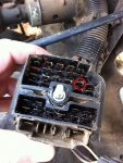
Try cleaning the connector that plugs into the alternator and cleaning up the spade connections.
I will be following this thread closely as I have 5 trucks that have varying degrees of charging discomfort and one truck that the needle and generator lights act exactly like it should so I will report back as I diagnosis each symptom and truck.


Last edited by a moderator:
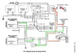
Here is the diagram with the GEN2 exciter wire.I changed the wire color to green to see it better. First thing to do is check the very bottom 24v fuse. If it is bad GEN2 won't work. And the GEN2 relay must be working.I've got an m1008. Gen 2 is getting 24v on the red wire in the back, but nothing on the brown when i turn the key. gen 1 is working properly. both dash bulbs are good. I've been trying to trace the brown from gen 2 to make sure the wiring is good, but i'm having trouble finding it where it goes through the firewall. Where does it go right when it passes through the firewall? thanks
Current flow is : fuse, GEN2 bulb, relay, diode, firewall and then the alternator plug.
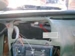
The brown wire comes thru the firewall and is part of the large wire bundle and works its way around the back of the engine and then to the alternator. The thick RED circle is the GEN2 terminal (ignore the thin red circle - it is a left over from another issue)
I'm sure you have read the first few pages of the troubleshooting section of the TM 9-2320-289-20 tech manual. It tells you how to read the diagrams and what all the wire labels and diagrams mean.
Attachments
-
60.2 KB Views: 253
-
83.6 KB Views: 208
-
60.8 KB Views: 230
Last edited:
badassissimo
New member
- 236
- 1
- 0
- Location
- Iowa, la
Definitely coming back to this after i get the new harness in.
- 34,010
- 1,827
- 113
- Location
- GA Mountains
Since this is a front page topic, what fails in the alternator (Alt 1) that will cause the gen 1 light to come on? The higher the engine revs, the brighter the light. Batt 1 shows 12.7V while not running and 13.8 while running. Odd.
- 34,010
- 1,827
- 113
- Location
- GA Mountains
Will swap it out and put it on the bench for a rebuild.
absher47
New member
- 3
- 2
- 0
- Location
- huntsville alabama
It was the fuse... of course i pulled the whole dash apart and was tracing wiring before i knew which fuse to check... thanks warthog, knowing which path the current takes really helped.
Lild
Member
- 68
- 2
- 8
- Location
- Nashville,nc
I was looking up alt for our trucks & came across this comp...http://www.cucvelectric.com/altcomplete.html
& found them here... Who would of thunk....http://www.amazon.com/ISOLATED-ALTERNATOR-10459234-1105500-321-744/dp/B008Y3NTAI
& found them here... Who would of thunk....http://www.amazon.com/ISOLATED-ALTERNATOR-10459234-1105500-321-744/dp/B008Y3NTAI
Lild
Member
- 68
- 2
- 8
- Location
- Nashville,nc
This was interesting read...http://67-72chevytrucks.com/vboard/showthread.php?t=453951
- 34,010
- 1,827
- 113
- Location
- GA Mountains
In trying to sound so technical, he failed to realize that he showed his ignorance.This was interesting read...http://67-72chevytrucks.com/vboard/showthread.php?t=453951
- Status
- Not open for further replies.
- 114,374members
- 167,249threads
- 2,354,519posts
- 4,790online users


