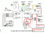
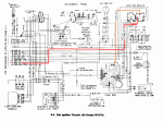
My point was not with bulbs so much as the potential confusion with including only the gen 2 bulb circuit - and only half of that, on E/F-4
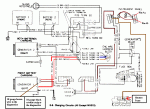
They couldn't put everything on each diagram. Diagram E/F-9 has the complete circuit for GEN2 and most of GEN1. Sometimes you have to look at many diagrams to "see" everything.

Yep you have found one of the flaws in the diagrams.
The complete circuit for GEN1 is not shown on any diagram.
If you look at the E/F-4 diagram you will see the "Heater blower" fuse is controled by the ignition switch. It feeds the right side of the heater fuse via the orange wire.
diagram E/F-20 shows the path of the heater coming out of the left side of the fuse via a brown wire 50A.
Diagram E/F-9 shows part of the GEN1 circuit. I have added some info to that diagram
What is NOT shown anywhere is the second brown wire also attached to the left side of the fuse. It is also brown and goes to pin #5 of the instrument cluster. Pin #5 supplies power to the GEN1 bulb circuit, the 4x4 indiator light and the Low Oil idiot light. If you trace a physical instrument cluster circuit board you can see that.
So the circuit for GEN1 is :
1 - Battery to 12v Terminal block on the firewall
2 - 12v Termninal Block to the Ignition switch (goes thru the firewall)
3 - Ignition switch to the Heater fuse
4 - Heater fuse to the instrument cluster connector #5
5 - Connector #5 to the GEN1 bulb
6 - GEN1 bulb to cluster connector #8
7 - Cluster connector #8 to the firewall plug
8 - firewall plug to GEN1 pin #1


