• Steel Soldiers now has a few new forums, read more about it at: New Munitions Forums!

  • Microsoft MSN, Live, Hotmail, Outlook email users may not be receiving emails. We are working to resolve this issue. Please add support@steelsoldiers.com to your trusted contacts.

Cucv glow plug wiring

jcollings

Well-known member
Steel Soldiers Supporter
560
391
63
Location
Jupiter/FL
Just received a new glow plug control module (card)
From previous conversations
It was said NOT to Rely on TM wiring diagram as shown.
As it shows resistor feed wire and small Orange wire coming from gpcm both connected together on gp solenoid large post. I do not want to damage the new module.
So to confirm Do NOT wire as TM
Indicates.

Thank you for any help.


Sent from my SM-G975U using Tapatalk
 

Curtisje

Well-known member
Steel Soldiers Supporter
596
693
93
Location
Okinawa, Japan
I don't understand the question. If you have a new card simply remove the old card and replace with the new.

What am I missing? Do you have an entire module housing that you have to wire in?
 

jcollings

Well-known member
Steel Soldiers Supporter
560
391
63
Location
Jupiter/FL
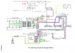
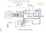
TM schematic is incorrect. The color one here is correct.

All of the Orange wires go on the output side (glow plug) of the GP relay. None of the Orange wires go on the resistor side.
Thank you so much, that's awesome and What I like to see.

Sent from my SM-G975U using Tapatalk
 

jcollings

Well-known member
Steel Soldiers Supporter
560
391
63
Location
Jupiter/FL
I don't understand the question. If you have a new card simply remove the old card and replace with the new.

What am I missing? Do you have an entire module housing that you have to wire in?
Well sometimes things don't appear as normal. Look closely


Sent from my SM-G975U using Tapatalk
 

Curtisje

Well-known member
Steel Soldiers Supporter
596
693
93
Location
Okinawa, Japan
I simply don't understand your question. Sorry to waste your time. I'm not going to waste mine studying your engine compartment. I have my own that consumes my time.
 

jcollings

Well-known member
Steel Soldiers Supporter
560
391
63
Location
Jupiter/FL
I don't understand the question. If you have a new card simply remove the old card and replace with the new.

What am I missing? Do you have an entire module housing that you have to wire in?
There is a additional wire (clamp) from driver side alternator, also a wire on the gp solenoid (clamp), they come together with a momentary switch. This is to start the Sequence Of glow plug start.
This is how I received vehicle.
As you said " Oh just put the glow plug card in in its all good" well I want to review the situation so I don't smoke up another card or other items worsening my situation. Now do you follow,

Sent from my SM-G975U using Tapatalk
 

MarcusOReallyus

Well-known member
4,524
816
113
Location
Virginia
You need to get that hack job out of there so you can troubleshoot properly.

  1. Restore the wiring to its original condition.
  2. Check for the correct voltage at the various glow plug terminals.
  3. Find the GP controller card connector under the dash.
  4. Disconnect the existing GP controller card, if it's still there.
  5. Identify the terminal which corresponds to the light blue wire (it goes out to the GP relay).
  6. Using a small jumper, connect that terminal to ground and verify if the GP relay engages.
  7. If it does, plug in a new GP relay card.

You should be good to go.
 

jcollings

Well-known member
Steel Soldiers Supporter
560
391
63
Location
Jupiter/FL
Yes,yes that's what we're working for. Hence why I ask about the correct diagrams, that antenna climber was so nice to send and show the links.

Know the set as you described,

Thank you

Sent from my SM-G975U using Tapatalk
 

Curtisje

Well-known member
Steel Soldiers Supporter
596
693
93
Location
Okinawa, Japan
There is a additional wire (clamp) from driver side alternator, also a wire on the gp solenoid (clamp), they come together with a momentary switch. This is to start the Sequence Of glow plug start.
This is how I received vehicle.
As you said " Oh just put the glow plug card in in its all good" well I want to review the situation so I don't smoke up another card or other items worsening my situation. Now do you follow,

Sent from my SM-G975U using Tapatalk
Cards expire without problems with wiring as well. But I agree it's smart to make sure it's correct before smoking another card.

And you exaggerated my reply a little from "If you have a new card simply remove the old card and replace with the new." to "Oh just put the glow plug card in in its all good". I'm only trying to help and it looks like Antenna Climber got you your needed info. I'll stop replying so that I don't cause you anymore frustration. Good luck sir.
 
Last edited:

jcollings

Well-known member
Steel Soldiers Supporter
560
391
63
Location
Jupiter/FL
You said I exaggerated your statement? I did say I wanted to review before installing the new card. If being cautious offend you I don't know that answer. I appreciate any decent constructive information.
You had mentioned you don't have time to waste to review the picture. I was just trying to give the analogy of the set up on how I received the vehicle and why I was trying to be cautious.
Have a great rest your day gunny.

Thank you!

Sent from my SM-G975U using Tapatalk
 

jcollings

Well-known member
Steel Soldiers Supporter
560
391
63
Location
Jupiter/FL
You need to get that hack job out of there so you can troubleshoot properly.

  1. Restore the wiring to its original condition.
  2. Check for the correct voltage at the various glow plug terminals.
  3. Find the GP controller card connector under the dash.
  4. Disconnect the existing GP controller card, if it's still there.
  5. Identify the terminal which corresponds to the light blue wire (it goes out to the GP relay).
  6. Using a small jumper, connect that terminal to ground and verify if the GP relay engages.
  7. If it does, plug in a new GP relay card.

You should be good to go.
Well verified all functions, on testing.
Glow plug solenoid did engaged, showed voltage but had week engage and disengage (sound) after a couple times.
Install of new card, Never seen a wait light. Truck started.
It's crazy when receiving the truck. It had a work around set up.. wiring from Gen. 1 ground to terminal other end of wirring to button then to light blue wire on solenoid. Turn the key, click the button , wait light came on , wait light went off, started truck with old card that was in place.??
I guess this is starting the wonderful world of problem solving .
Also showing 26 v at glow plug solenoid feed while truck running???? .
Verified temperature ohm reading on glow plug card temp sensor.
I suppose I'll order a glow plug solenoid , anyone have the correct part number would be helpful, or maybe I'll just pickup a generic one.

Thank you


Sent from my SM-G975U using Tapatalk
 

jcollings

Well-known member
Steel Soldiers Supporter
560
391
63
Location
Jupiter/FL
So no specific , like I've seen some people advertise there's one for $80 that's the right one. compared to $25 for generic

Sent from my SM-G975U using Tapatalk
 

jcollings

Well-known member
Steel Soldiers Supporter
560
391
63
Location
Jupiter/FL
Yeah I seen an earlier post from you about that. it made me feel better and less concerned.

Sent from my SM-G975U using Tapatalk
 

Jake59

Active member
170
102
43
Location
Kaggevinne, Flanders, belgium
TM schematic is incorrect. The color one here is correct.

All of the Orange wires go on the output side (glow plug) of the GP relay. None of the Orange wires go on the resistor side.
Hi Antennaclimber,

Had a look at the wiring diagram here and compared with the actual wiring in my M1009.
Please see attached picture, Green arrow and circle near the bottom.
May I ask you to have an expert look at that connection?
Could it be that GM by mistake crossed the wires in the green box, when they were drawing the diagram?
There are physically 2 black wires coming off the first (bottom) post which is the "ground", so I understand and the yellow wire from the temp sensor goes to the second post, which then is "Temp Sensor (+)".
Not that this is a major change but for correctness, in particular for simple minds like myself, who have a hard time understanding any electronics and schematics...

Thank you,
Jake
 

Attachments

antennaclimber

Moderator
Moderator
Steel Soldiers Supporter
1,367
949
113
Location
State College, PA
Congratulations Jake, you found one of two errors with the drawing. The + side of the temperature sensor is the one that is not tied to ground.
I also noticed this mistake a few years ago but never thought it was worth mentioning.

So to clear things up:
The .8 BLK wire should go to ground and .8 YEL wire should be the TEMP-SNSR +

There is one other minor mistake with that drawing but it is simply a labeling error with an unneeded line. Let's see if someone can identify it.
 
Top