- 579
- 421
- 63
- Location
- Jupiter/FL
Just received a new glow plug control module (card)
From previous conversations
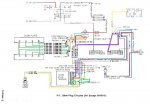
It was said NOT to Rely on TM wiring diagram as shown.
As it shows resistor feed wire and small Orange wire coming from gpcm both connected together on gp solenoid large post. I do not want to damage the new module.
So to confirm Do NOT wire as TM
Indicates.
Thank you for any help.

Sent from my SM-G975U using Tapatalk
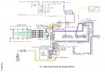
From previous conversations
It was said NOT to Rely on TM wiring diagram as shown.
As it shows resistor feed wire and small Orange wire coming from gpcm both connected together on gp solenoid large post. I do not want to damage the new module.
So to confirm Do NOT wire as TM
Indicates.
Thank you for any help.

Sent from my SM-G975U using Tapatalk

 just order,