• Steel Soldiers now has a few new forums, read more about it at: New Munitions Forums!

  • Microsoft MSN, Live, Hotmail, Outlook email users may not be receiving emails. We are working to resolve this issue. Please add support@steelsoldiers.com to your trusted contacts.

Electrical

MarcusOReallyus

Well-known member
4,524
811
113
Location
Virginia
There's learning differently, and there's just plain wrong. His description is just plain wrong. The CUCV 24v circuit is NOT isolated ground. The CUCV 24 volt systems use chassis ground.

Here's a quick overview. I haven't put in the GP circuit or alternators. I'll try to come back and add those.
 

Attachments

PeeWeeQ

Member
161
4
18
Location
Altoona, WI
Alright... Lemme back up a bit. You CAN'T have a completely isolated ground system. There HAS to be a reference (measuring point) to the ground.

That said, showing a diagram without a ground reference (drawn or worded) can help to illustrate a series circuit between two supplies. The only thing that is truly isolated from the ground on a CUCV, as I understand it and have experienced the hard way, is Gen 2. The reason is because a 2nd battery has been added in order to add 12 more volts of "pressure" to the starting and GP circuits. Simply put, you can't charge 24 volts of battery with 12 volts of generator, even if both batteries are 12 volts apiece...

Sent from my SM-G920V using Tapatalk
 

MarcusOReallyus

Well-known member
4,524
811
113
Location
Virginia
Alright... Lemme back up a bit. You CAN'T have a completely isolated ground system. There HAS to be a reference (measuring point) to the ground.
Ah, sure you can! It's electrically simple, but it's a pain to do. You have to be really careful with the routing of every wire and every mounting point. However, they do exist. I just haven't seen any in automotive use, that I can remember.

Here's what confuses most folks. We use the term, "ground" as if it means the same thing as the chassis, but it does not.


That said, showing a diagram without a ground reference (drawn or worded) can help to illustrate a series circuit between two supplies.
I think it just confuses the issue.

The only thing that is truly isolated from the ground on a CUCV, as I understand it and have experienced the hard way, is Gen 2.
Yep.


Battery circuit diagram 1.jpg
 

Attachments

PeeWeeQ

Member
161
4
18
Location
Altoona, WI
I'll just say that if you don't have a grounding reference to the chassis, you'll wish you did the first time you BECOME it...

Earth, chassis--all references to ground. But, you made my point with one word--"SIMPLE". That's what I was getting at. It's easy to see how things work in theory or concept, the more simple the circuit, even if it's not realistic or practical....

Great discussion...!

Sent from my SM-G920V using Tapatalk
 

MarcusOReallyus

Well-known member
4,524
811
113
Location
Virginia
There's a huge difference between ground in a vehicular system and ground in a power system. In a power system, ground is pretty much absolute, but only because we use the actual ground as part of the circuit. We must avoid contact with power sources because we are almost always in contact with the other side of the circuit - the ground. Personal contact with that ground part of the circuit is our norm - we live that way, and we must take special precautions to isolate ourselves from that part of the circuit when working with the other side of the circuit.

In a vehicular system, there is no such absolute reference. Yes, the ground is usually the chassis, but it doesn't have to be. We choose to do it that way for cost savings. By using the chassis as the ground, we save the cost of running wires to complete every circuit, plus the design is much simpler. Since that choice is pretty much universal, most people assume it has to be that way, but it doesn't.

In fact, it would be quite easy (in principle) to have an car or truck built where the chassis is no part of the electrical circuit. We could have 5 different voltages, and a mix of polarities, and even AC mixed with DC systems, with no problem. Each separate system would have its own ground reference, which would have nothing to do with any other system's ground reference. So you could measure from the positive terminal of System 1's 48v battery to the negative terminal of System 2's battery and see 0 volts.

We don't do that because there's no benefit to it, and it would cost more and make things more complex.
 

PeeWeeQ

Member
161
4
18
Location
Altoona, WI
Your explanations are excellent...I'm loving this discussion, however, I have to get back to my electrical troubles...Some theory may come into play here...

My alt parts aren't here yet, so, I decided to go through voltage checks again--By the book this time--no John Wayne-ing it

Pulled the excitor connectors off each Alt. Checked voltage on each of the red wires first with the key off. 12.8 volts on Gen 1 side and 25 volts on the Gen 2 side. Turned the key on and measured voltage at the brown wire on each. 12.6, or so, volts on Gen 1 side and only 17-18 volts on the Gen 2 side. Traced back to the diode behind the voltmeter--17-18 Volts. Relay--17-18 volts. At the fuse block--25 volts...SOOOO, my problem is in between the Gen 2 relay and the fuse box.

I thought it was probably the PCB, so, I pulled it and checked the contacts, bulb, and socket for the gen 2 light--I measured the resistance on the circuit between the harness contacts for Gen 2. I got 32 ohms. All the others were around 7 or 8 ohms. Sooo, I soldered in a couple jumper wires. Dropped the resistance down to 7 or 8 ohms, but, to no avail.

Any ideas where I would be getting a 6 or 7 voltage drop...? Need a new PCB or what?
 
Last edited:

PeeWeeQ

Member
161
4
18
Location
Altoona, WI
Got back to it today...

Put a new PCB in in order to eliminate that possibility. Not the problem. Bulbs and sockets check out, so, I decided to check voltage at the wiring harness. Pin 7, where it plugs into the PCB has 25 volts with the key on and pin 6 shows 12 volts. Shouldn't pin 6 show 25 volts and pin 7 show 0 volts with no PCB to run through since the circuit runs pin 6, through the bulb, then out pin 7 to the relay?

What could be the problem here? Shorts in the wiring harness?

I feel like I'm close, but, I don't know where to go next...

Sent from my SM-G920V using Tapatalk
 

PeeWeeQ

Member
161
4
18
Location
Altoona, WI
Good news!


There it is... :doghead: 
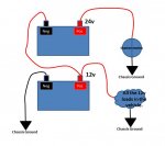
I traced the circuit (found out that 24 volts actually goes INTO the PCB via pin 7 (orange wire), through the Gen 2 bulb, and OUT via pin 6 (BRN/RED wire) to the relay.

I don't know where I was getting that 12 volts there or why, but, it disappeared. I checked for continuity between all wires and the Gen 2 relay socket. Then, turned on the key, had 12 volts at the pink/black wire, 24 volts at the brown/red wire, ground was good, and continuity from the 24V output on the Gen 2 relay socket to the diode.


Everything looked good, so, I decided to try the relay (note: I had replaced the Gen 2 relay last year and bought spares). I paused, and before putting the one I had taken out back in, I decided to go into the garage, get a new one, and try it. I plugged it in, turned on the key, and WHOLLA! First time I'd seen my Gen 2 light in almost 4 years. I don't know how or when that relay went bad (maybe it was bad right out of the box), but, I'm glad I decided to try a new one!

I charged up the batteries for good measure and fired it up. I'd recently done the Doghead starter relay mod, paired that with my recent addition of an electric fuel pump, and WOW--did it ever spin over nice. Gen 2 light went out with Gen 1 and the Voltmeter was well into the green...

Thanks for all the help, Gents! I can't even begin to describe the elation... Now, it's time to put it all back together again.

After all this messing about, I can say one thing with confidence--I am now certain that I know and understand the charging system and it's related circuits quite well. I made lots of mistakes along the way, but, I learned much, much more. Hopefully, this will give me the ability to help someone else with their troubles...

I'm not even sure what it is EXACTLY that fixed the original Gen 2 light--it may have been the first or second rebuild, the last diode trio replacement, OR, could it have been that the replacement GEN 2 relay was bad? Maybe it was both. :shrugs: I'll never really know, but, I do know how I'll go about figuring it out next time--hopefully for someone else!!!
 
Last edited:
Top