- 312
- 156
- 43
- Location
- Sweeden, KY
I had a failure of the PCB in my M925A1 last year. As part of the troubleshooting, I made some notes and took some pictures, attached. Mine was the type with a circuitboard. Hopefully the wiring diagrams will be helpful to someone in troubleshooting. I also put together a little troubleshooting guide, which goes to the extent of taking the box apart and checking the individual relays. The relays can be purchased individually fairly economically. In my case the main power relay was bad. I noticed that that model was an Ametek SAS-4418, which is a heavy duty intermittent relay, only rated to be energized 10 minutes at a time. So I replaced it with a SAS-4410, better rated for the application, i.e. continuous duty, more appropriate for the main power relay. Info at texasindustrialelectric.com.


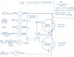
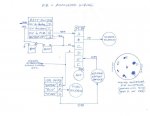
View attachment PCB Troubleshooting.docx
As has been noted in other threads, the PCB provides protection against polarity errors and energizing the starter while the engine is running (signal from alternator to Terminal F). In the event of circuitboard failure, it would be pretty easy to rewire the box to bypass the circuitboard and directly energize the relays from the inputs to the box, but then those protections would be gone.
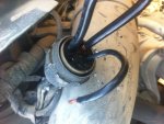
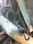
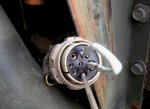
As far as emergency bypassing in the event of failure, you can connect the C & D terminals, the large wires, to replicate the function of the main power relay, then just jumper the starter. You also need to power the fuel solenoid to make the truck run, which can be done with the normal "RUN" switch position on the ignition switch once the main power relay is jumped. Keep in mind that alternator output will go through the jumper so it needs to be substantial. Just for kicks, I made a jumper out of 1/4" steel tubing, stuck it in the PCB plug sockets for Terminals C&D. Ignition switch on, then short the jumper to Terminal B (wire 74) with a screwdriver, the truck fires right up. Just keep in mind the jumper is electrically hot, and be careful handling it especially in the rain; 24 VDC can shock under the right conditions. See picture:
It seems the PCB enclosures may be put together a couple of different ways. I cut mine apart with a thin cutoff wheel in a side-grinder, then tack-welded it at four locations and JB-welded the gap all around.


View attachment PCB Troubleshooting.docx
As has been noted in other threads, the PCB provides protection against polarity errors and energizing the starter while the engine is running (signal from alternator to Terminal F). In the event of circuitboard failure, it would be pretty easy to rewire the box to bypass the circuitboard and directly energize the relays from the inputs to the box, but then those protections would be gone.
As far as emergency bypassing in the event of failure, you can connect the C & D terminals, the large wires, to replicate the function of the main power relay, then just jumper the starter. You also need to power the fuel solenoid to make the truck run, which can be done with the normal "RUN" switch position on the ignition switch once the main power relay is jumped. Keep in mind that alternator output will go through the jumper so it needs to be substantial. Just for kicks, I made a jumper out of 1/4" steel tubing, stuck it in the PCB plug sockets for Terminals C&D. Ignition switch on, then short the jumper to Terminal B (wire 74) with a screwdriver, the truck fires right up. Just keep in mind the jumper is electrically hot, and be careful handling it especially in the rain; 24 VDC can shock under the right conditions. See picture:

It seems the PCB enclosures may be put together a couple of different ways. I cut mine apart with a thin cutoff wheel in a side-grinder, then tack-welded it at four locations and JB-welded the gap all around.


