• Steel Soldiers now has a few new forums, read more about it at: New Munitions Forums!

  • Microsoft MSN, Live, Hotmail, Outlook email users may not be receiving emails. We are working to resolve this issue. Please add support@steelsoldiers.com to your trusted contacts.

First Post - Introduction - My MEP003 Saga to Date...

NJ_Toolnut

New member
83
0
0
Location
Bloomsbury, NJ
Thanks Richard,

I was aware that it uses an Onan DJF engine before I purchased it. I was not aware Onan began producing them about 1970. I think (based on the initial dates in the TMs) the DOD started purchasing them around 1977. Unfortunately, the civilian models that wait quietly seldom advertise their presence.

Thanks for confirming my understanding regarding the Onan parts numbers listed in the TMs.

This part of my response is getting a little philosophical, but I'm OK with that. Unless I have a compelling reason not to, I try to do things as well as time, my ability and my wallet permit. Life is too short for rework, since I usually have so many projects going on simultaneously that I feel as though I can't afford the time spent doing rework. Sure, I want to make electricity, but I also want a completely reliable genset. I did a lot of research on generators before I acted, and this was why I selected a military surplus generator, an MEP003 instead of a different military surplus model and also one that recently had a Tier 2 reset (I knew it was still a crap shoot and unfortunately for me, I rolled snake eyes). By fixing it as well as I can, I'm hoping to ensure reliability. I want to fully understand how it works in order to be sure I know what I'm doing in order to do it as well as it can be done, but I also want to get it done in a reasonable amount of time. In addition, fully understanding how it works will ensure my ability to fix it if something else breaks. Hopefully, all it will require in the future is routine maintenance so that I can move on to other interesting in-process projects, like learning how to weld and finishing rebuilding my huge old metal shaper and pedestal grinder.

This is my first experience with green iron, but I've always been interested in it because I'm attracted to the promise it seems to have for ruggedness and reliability. I would classify myself as more of a "fixer" than a "tinkerer", but working on old machines sometimes presents the appearance of tinkering, since it frequently becomes necessary to keep them apart for long periods of time due to parts sourcing challenges. That's one reason why being able to do machining is valuable.

Best regards,
Stan
 

RichardR

Member
96
3
8
Location
Austin, TX
Stan,

You have a good understanding of how to time the IP. The first step is to make sure the correct shim (between the IP base and the machined mounting face on the block) is in place. As you surmised, that shim determines the gear lash between the IP and camshaft gears. The shim thickness is determined at the factory for each new block, and so the shim goes with the block. The one you got from storeman with the block is surely correct, but you can check it if you have the proper micrometer. The measured dimension, as shown in TM5-6115-585-34, Figure 7-33A, is 1.171 inches between the camshaft (next to the IP drive gear) and the outside face of the shim.

Getting the correct button is somewhat more of a problem since you have to install the pump and measure the timing, then, if the timing is not "right on", determine how much the button needs to be changed. How lucky would you have to be to get it right on first install!

I think you need to use the "flow" method since the "calculation" method can only be done if you have the old, correctly timed IP that is being replaced. You don't have the old IP from storeman's block, do you? Besides, the "flow" method makes sure you have it right when you are finished. You actually measure the final timing with the "flow" method.

You start by looking at the installed button (or trusting the stamping on the pump flange) to get the initial button thickness. I'd guess that the stamp on your pump flange is "13" (rather than 1 or 3) since the factory suggested starting button is 11. (I don't quite understand the table in the TM.) Then the flow method as described in the TM tells you how much to change it to get the right timing. Sounds pretty simple, doesn't it? Probably a lot harder than it sounds, but it can be done.

Unless you are really lucky, you are going to need a different button. Ambac is the only sure source that I know of, but like all the other pieces of that engine, there must be lots of stray buttons floating around. Ambac will be expensive. I have (rarely) seen complete sets of buttons on GL. Maybe Onan is a source if they still support that IP, but they will be expensive, too. And then there is your local IP rebuild shop.

You're doing a great job and, no doubt, having lots of fun with your new toy.

Good luck,
Richard
 

NJ_Toolnut

New member
83
0
0
Location
Bloomsbury, NJ
Thanks for your excellent post, Richard. What you wrote is very clear and perfectly logical.

Since I don't have Jerry's IP, I could ask him if he knows what its button number and port closing dimension were, but I agree the only way I will ever ultimately know for sure whether my IP is timed correctly is to flow it (Method 2). If I discover that I need a different button as a result, than I will cross that bridge when I come to it. I will have to start with the button I currently have instead of a #11, but I think I should remove the one I have from the IP first and measure its thickness to confirm it is really a #13 (assuming it is unworn), so I can be confident in the result I get from flowing the IP that is used to choose the correct button. Maybe once I install the presumed correct button, I should flow the IP once more for confirmation, since timing is so critical.

It appears that the variations in the stackup of all the tolerances in all the parts involved that ultimately determine the port closing dimension, coupled with the IPs short piston stroke are what caused this IP to require so many different timing buttons.

Yeah, I'm having fun, but I'm also a little stressed out about having made a relatively large investment for what is currently a lawn ornament. I will only be able to acknowledge having done a great job after I've completely wrenched this genset together again and started and run it for a few hours under load. I'm still very confident I will prevail since this machine is reallly not that complex. The ultimate goal is reliable back-up electricity availability. Having fun is a welcome by-product though!

I meant to ask: How did you make out with your generator engine in crate purchase? Have you picked it up yet?

Best regards,
Stan
 

RichardR

Member
96
3
8
Location
Austin, TX
Stan,

You take out the installed button for inspection by first pulling/prying out the tappet in the middle of the circular gear. The tappet comes out fairly easily since it has only an o-ring holding it in. Then the face of the button is exposed, but there is a circular springy wire clip holding the button in that must be removed in order to take the button out. BE CAREFUL taking that springy circular wire clip out, or it will fly off to parts unknown and never be seen again. Lots of folks lose that clip!

Then the button will drop out. You will find a VERY SMALL stamped number or letter on the button side. That's the button size identifier. The button is made of very hard material so I wouldn't worry about possible wear and actually measuring its thickness.

Reassemble in reverse order, again being careful to get that cursed circular retaining spring into its proper home without it escaping.

One other thing we haven't covered is how to be sure the Port Closing (PC) pointer (the pointer over the hole where you see the flywheel and its PC mark) is in proper position. That pointer can be loosened and moved or bent. If you want to be sure the pointer is in proper position, there is a procedure in the -34 (Figure 7-4 and surrounding verbiage) for setting the engine to exactly the PC rotation angle independent of the IP. At that engine rotation angle, the pointer should align with the PC mark on the flywheel. If not, the pointer needs to be adjusted. It's a fair amount of trouble to do all this, but since you have the engine pretty well apart and are "doing it right" you might want to take a look. There's little point in setting the IP timing to PC if the PC mark you are working from is incorrect.

The rebuilt engine I bought from GL a few weeks ago was pretty much as I expected. It is indeed a "fresh" rebuild, about 5 years since rebuild but probably still OK since all ports are covered. Also as expected, it is stuck from sitting in the same position for so long, and I didn't try very hard to turn it since I won't be using it immediately. I am reminded once again that the GL pictures almost always look better than real life. It has a few minor dings and lots of CARC sprayed everywhere. I expect it will work fine when needed.

Regards,
Richard
 
Last edited:

storeman

Well-known member
1,345
52
48
Location
Mathews County, VA
Stan,
Glad you are progressing. Pat and I enjoyed meeting you and your daughter.

Four pushrods from smw70ss cost $29, again not counting shipping. I don't think I got fleeced, but if I was wiser about sourcing I probably could have saved some $.

I wish you had contacted me for the push rods and the housing, et al. I have several good ones just occupying bench space. Let me know if I can be of help.
Jerry :beer:
 

joesco

Member
442
1
18
Location
Hampstead, NH
Stan,
Just be aware that the timing button can be had from Ambac, but they cost $45-$70 a piece. I have found they are open for negotiation. If you call them don't pay list price and make sure you order a few "Jesus" retainer rings as they tend to go airborne when you are installing the button!
 

NJ_Toolnut

New member
83
0
0
Location
Bloomsbury, NJ
Thanks Guys!

Richard,

I appreciate your detailed description on removing the timing button. I also recall reading joesco's description in his HUGE thread in which he called the little circular wire clip a "Jesus" clip. I got a chuckle out of that!

I looked at Fig. 7.4 in TM-34 and re-read the surrounding verbiage. I will first check my replacement block to see whether the line on the back of the pointer is in alignment with the line stamped adjacent to it on the engine block, but it seems wise to go through the procedure as well. I will need to modify the procedure however, since with the cylinder head off I can index my dial indicator directly on the top of the piston instead of on the end of the exhaust valve stem.

FYI, I also went through the procedure for measuring/calculating the gear lash for the IP. I was looking for the 0.014" dimension stamped on the replacement block and instead I obtained 0.008" but I don't trust my depth micrometer very much and I also found it very difficult to precisely locate the depth micrometer stem in exactly the correct location on the surface of the IP gear attached to the cam. For this reason, I'm going to trust the 0.014" dimension stamped on the block instead of the 0.008" I measured.

I'm glad you got what you expected from GL with your "engine in a crate" crap shoot. I certainly agree that the CARC paint is a real pain in the a$$ to get off nuts and bolts. It's the toughest paint I've ever seen by a longshot, and I wish I had some. I remember reading somewhere herein that it is very hazardous to spray, however.

Jerry,

Progress seems slower than I would like since my real job takes most of my time, but I hope to make some good headway this weekend. It was a pleasure and an honor to meet you and Pat, and I would very much like to visit you again sometime. Rachel loved Pat's speghetti and meat balls, and I thought they were delicious as well. If it is not too much trouble, would you mind emailing me the receipe sometime?

Quite frankly, I did not even think of you with regard to sourcing replacement pushrods. I guess I must have assumed your pushrods got used in conjunction with the cylinder heads when you parted out this machine. The only other things I bought were gaskets, no housings. I hope you are not offended, and I promise to consider you first if I need anything else.

Joesco,

Thanks for letting me know AMBAC will negotiate on timing button prices, since I will very likely need one, as well as some "just in case" "Jesus" rings. I was following your IP sale on Ebay and I was surprised to see the price you got for it. I hope you recouped your investment.

Thanks again for your interest and assistance. I will post next week to update you on my progress this weekend.

Best regards,

Stan
 

storeman

Well-known member
1,345
52
48
Location
Mathews County, VA
Stan,
Not offended at all. I would have given them to you when you were here, had I known you needed them. I have several heads but haven't listed them. Pat will send you the recipe.
Jerry
 

NJ_Toolnut

New member
83
0
0
Location
Bloomsbury, NJ
Hi Everyone,

This is a quick update to respond to storeman, provide current status and make a request while waiting for my wood stove to warm up my workshop (the temperature is only 11 degrees here this morning).


Jerry, I thought back through the sequence of events that occurred prior to visiting you. At the time of our visit, I did not yet know I had bent pushrods since I had not yet removed and tested them (although I suspected it, based on Keith's post).

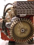
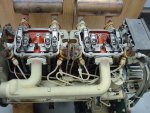
I made good progress yesterday. The replacement engine block is almost completely "dressed up" except for installing the rocker covers, shrouds and a few other parts. I may wait until I've rigged it onto the trailer and connected it to the generator to install the shrouds in order to make it less awkward to handle. Here are a couple of images:

Progress Front of Engine.jpgProgress Top of Engine.jpg

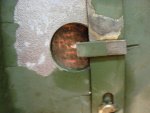
I performed the calibration of the flywheel pointer to the port closing mark using the test indicator method described in TM-34, with the following result:

Port Closing Test.jpg

The camera angle is not exactly horizontal and as a result it makes the pointer look lower (more retarded) than it actually is. The pointer is actually about the width of the stamped mark lower than the existing mark. I'm not going to change the pointer location for two reasons: First, I don't know how repeatable this test is since I only performed it once. Second, I don't believe the difference between the result I obtained and the current pointer location is large enough to matter.

When I went to install the rocker arms, I found the following:

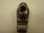
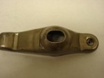
Cracked Intake Rocker Arm.jpgCracked Exhaust Rocker Arm.jpg

The cracked intake rocker arm is from the #1 cylinder which had a bent pushrod, and the cracked exhaust rocker arm is from the #2 cylinder which also had a bent pushrod. Apparently the pushrods did not bend soon enough to absorb all of the energy caused by the impact of the piston on the face of the open valves. I installed these cracked rocker arms in order to lash the valves and observe the action of the valve train when barring the engine over, and all appears normal, with good compression on all four cylinders. I think it would be very risky to actually run the engine this way, though. Does anyone have any used rocker arms?

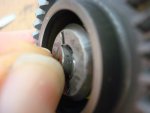
I pulled the tappet out of my IP in order to see which timing button was installed. I discovered that I could see the number stamped on it without removing it from the IP (thereby avoiding the need to deal with the "Jesus" clip):

Timing Button 14.jpg

The stamped number is almost too small to read without magnification and is also little difficult to read in this image, but the timing button currently installed is button number 14. It will be useful to have this information when I time port closing via the flow method (Method 2).

Best regards,
Stan
 

NJ_Toolnut

New member
83
0
0
Location
Bloomsbury, NJ
Hi Everyone, time for an update.

I sourced the two rocker arms I needed from Delk's. They were take-outs, but barely worn. Cost was $12 each. I thought this was a good deal.

I installed them, re-lashed the valves, installed the rocker arm covers and lifting bracket, installed the engine to the generator on the trailer, installed the batteries, fuel tank, starter, etc, etc. Getting this all done took the entire day on Saturday. Yesterday I timed the IP using Method 2. I performed the procedure exactly as described in TM-34. I got a good flow of fuel from the #1 injection line without the need to keep the delivery valve holder loose--I removed the delivery valve cap, holder and spring and replaced and re-tightened the delivery valve holder without the spring per TM-34. I was not expecting the stream of fuel from the #1 injection line to be as strong as it was, so I made a little mess on the trailer deck since I had my fuel receiving pan in the wrong spot. I had the #1 injection line positioned horizontally, and the flow of fuel from it was close to two feet long. I barred the crankshaft over very slowly until the flow stopped, and I performed two trials. The first time, the PC mark wound up 1 1/4 marks below the pointer and the second time, the PC mark wound up 1 1/8 marks below the pointer. So the IP was closing slightly early, and therefore needs a thinner button by one mark (0.006"). Button thicknesses increment by 0.003" and I currently have button #14 (0.128") installed, so I need button #12 (0.122"). I ordered one today from AMBAC (along with a package of 10 "Jesus" clips). If any one needs a couple of these clips for free, just PM me with your address. I got the button for half price (38 dollars) from the nice lady I talked with on the phone. :mrgreen:

Since the IP timing was off by only one mark, I decided it would not hurt the engine to attempt to start the genset, and it fired right up! It produced a great amount of blue smoke at first until it burned off the oil coating the cylinder walls and piston tops, but then it ran without producing any smoke. Oil pressure was initially 50psi. It also surged up and down by about 50-100 rpm in a very regular manner for every second or two for the first ten minutes or so, possibly due to an air bubble trapped somewhere in the high pressure side of the IP, but then the rpm smoothed out completely. I ran it for about 30 minutes while checking for leaks and confirming current production (I had an electric space heater plugged into the convenience receptacle). Once it warmed up, oil pressure was 40psi. Then I shut it down, checked the oil and added some (it was a quart low, I think due to the oil lines, filter cannister and oil cooler having previously been empty) and wired it up for load testing. I then fired it up and load tested it using the baseboard electric heat in my workshop and the rotary phase converter/electric motors on my machine tools.

I noticed a couple of things. First, compared to the old engine, this one does not recover as rapidly from a sudden heavy load. My biggest single load is currently the 5hp 3-phase motor on my lathe. It is a very old motor and it has a really heavy rotor. As a result, it must have a really large inrush current on startup, even though it pulls only about 15 amps (three phase--more like 25 amps on the single phase side of the rotary phase converter) at full motor load. After having been significantly preloaded with baseboad electric heat, it took the old engine only about a second to recover from this sudden heavy additional load, but it takes the new one 2-3 seconds, after nearly stalling. I'm thinking this could be happening due to my IP not being correctly timed, do you agree that this is most likely the reason?

Second, I noticed that the governor did not compensate very well (if at all, at least at first) for load increases. I set the no load rpm using the frequency meter so I was getting exactly 60Hz, then loaded the genset to about 65% rated amperage. Frequency was then down to about 56Hz. I read about adjusting the governor in the TM-34, but this part does not appear to me to have been particularly well-written. It appears that the TM-34 calls this genset behavior "droop". I tried lengthening the linkage between the IP control shaft and the governor arm by about 1/4" in an attempt to correctly set governor overshoot and undershoot, checked to make sure I had no clearance or sticking issues, changed the positon of the heavy spring so that its hooked end that attaches to the spiral shaft of the governor arm was lower below the droop adjust ratchet, rotated the droop adjust ratchet 1/2 turn clockwise, reassembled the blower shroud, and re-tested. I'm still getting a droop of about 2Hz at 65% load, but quite frankly I don't know what I'm doing with these governor adjustments. Can anyone please clearly describe the process of adjusting the governor? I ordered a kill-a watt meter today in order to test the frequency meter, since I really need to confirm it is correct in order to be sure I'm really governing the engine at 1800 RPM.

Bottom line: I still have some relatively minor wrenching ahead in order to install the correct timing button, and I still have some governor tweaking ahead, but I'm very happy with this progress!

I'd like to thank storeman again for the wonderful deal he gave me on his spare short block, and I'd also like to thank everyone who contributed to this thread for helping me very quickly surmount my learning curve. I still have a lot to learn about these gensets, but I hope to someday be able to make a meaningful contribution to this forum.

Best regards,

Stan
 

joesco

Member
442
1
18
Location
Hampstead, NH
Stan,
I was having the same problem with my 002A and made several adjustments to the governor adjustment, to no avail, probably had no clue as to what I was doing! I ended up overheating my IP due to improper timing or a wrong timing button (or both). If you do another test run, please check to make sure your IP is NOT hot or you could be digging (deeply) into your wallet again. IMHO, I would not run the set again until you are absolutely sure you have the correct timing button and the engine is timed correctly. Again, I am amazed at your progress and determination. Great Job!!
 

RichardR

Member
96
3
8
Location
Austin, TX
Stan,

Well, I have to admit that I am impressed both with your mechanical abilities and your progress in getting your genset back together. Lesser folks would have thrown in the towel long ago, but you are within sight of the goal and about to cross the finish line! Even the PC timing measurement you made seems to have worked right according to the instructions. Many of us have had issues following those instructions.

You have apparently learned very well how to shop for the parts you need, having charmed the nice lady at AMBAC into giving you the lowest price I have ever heard on a new timing button. I had to pay $15 plus expensive shipping for an Oldham Drive (plunger guide) that you could probably have gotten for $5 plus first class postage!

It sounds to me like your engine is running reasonably well with the timing as it is. It will, no doubt, improve with the correct timing, so I wouldn't be concerned about the governor response you are seeing.

You asked about the governor adjustment procedure. It sounds like you already have a good idea how to do it, and a 2 Hz drop (droop) from 0 to 65% load is about what you should expect to achieve. You can try to make the droop less than 2 Hz by adjusting that big spring on the Droop Adjust Ratchet (that coarse threaded shaft), but adjusting for less droop may cause hunting. At the same time you want to have the Governor Arm near the center of its travel. The Governor Arm position is adjusted by the link length. If the Governor Arm bumps against one of its limits, you will get too much (perhaps violent) overshoot or undershoot. Sorry, I can't explain it in step-by-step fashion, but what you want to achieve is sufficiently low droop but no hunting (set by spring position on Droop Adjust Ratchet) and Governor Arm near the center of its travel (set by link length).

And if you run out of link length adjustment travel, you can get all the travel you need by slightly bending the Governor Arm.

In any case, I wouldn't get too hung up on adjusting the governor just yet. It will run differently when you get it timed right.

Good luck with finishing up this complex repair. You are way ahead of me. In fact, I consider you now to be the official knowledge source on MEP-002A and MEP-003A engines. And, certainly, you know how to talk to the nice lady at AMBAC. I'm sure I'll need your services sometime soon.

Regards,
Richard
 

NJ_Toolnut

New member
83
0
0
Location
Bloomsbury, NJ
Joe,

Thanks for your praise. Given the magnitude of my investment, failure was not an option.

I appreciate your concern. I remembered from your long post the trouble you described with your IP getting hot, so it was one of the things I monitored as my unit was running after completing all the work required to fix it. My IP did not get significantly warmer to the touch than the engine block next to it, even after three hours of operation.

Richard,

I really appreciate your kind words. While it is true that I have lot of intrinsic mechanical aptitude, I've also been playing with machinery since I was a child with my first Erector set. Then, as a young adult (many years ago), I rebuilt a chevy small block V-8 from the crankshaft out, with oversight from a mentor who happened to work with me at Buick, in Flint, Michigan. He was a mechanical engineer and graduate of General Motors Institute. We were both into drag racing back then. I worked at Buick for about ten years through the 1970's, doing final assembly, paint and repairs on Electras, LeSabres and Riverias. It was so long ago that front wheel drive cars had not yet hit the US market. Troubleshooting and fixing things that didn't work correctly following assembly was particularly challenging. Those experiences did a lot to endow me with mechanical knowledge, and quite a lot of it was directly transferrable to this project. The most important things I have learned from working on machines are to think logically and to take things one step at a time while never losing sight of the larger picture and the objective.

The nice thing about a board like this is that we are all official knowledge sources. What I mean is that the whole body of knowledge we share here is much greater than any amount of knowledge we could ever possibly acquire by ourselves. I don't consider any of us to be actually ahead of any one else in terms of overall knowledge, since we have all had unique experiences with these units. For example, I know next to nothing about the electrical side of these units, since I have not yet had the need to delve into this part of their operation. It took me a couple of hours studying the schematic before I even understood how the generator works. However, I can certainly describe in great detail how to change cylinder heads. It is a huge force multiplier to have access to the entire body of knowledge available on this forum. It also works wonders on confidence. Maybe I should buy an M35A2 now!

Frankly, I just got lucky with AMBAC, and almost incredibly lucky in obtaining the short block from Jerry. I still have a lot to learn about parts sourcing. I like Delk's.

Thanks for your governor adjustment description. It confirms what I thought I may have deduced from reading the TM-34 and observing the governor's design features and actions. Although I've only had limited experience with governors (mainly very simple governors on B&S lawnmower engines) the one on this unit does not appear to be all that complex by comparison. However, I've already noticed it has some additional subtleties. I think what I will need to do is vary each adjustable parameter alone through at least part of its range (keeping the others constant) while observing its effect so I can get the sense of what it is intended to furnish (in terms of control). I just need to re-read TM-34 and keep in mind what I need to be careful to avoid over-adjusting in order to avoid a runaway situation. Once I have done this, I should be able to grasp the overall adjustment strategy. I'll be sure to share my experience with it. I agree that doing any optimization in terms of governor adjustment without getting the IP timing correct first would be largely (except for the knowledge gained) futile. All I've really done so far is to try to get a feel for it. It will be very interesting to see whether there is a noticable improvement over the engine's current performance once I've installed the correct timing button (and confirmed it is correct).

Best regards,

Stan
 

Crawdaddy

Member
444
4
18
Location
Louisiana
I've read a few times about making sure the IP doesn't get excessively hot, but I don't recall seeing what the acceptable temperature range for the IP while running is or how hot is too hot. I definitely want to monitor the IP temps and general engine temps for the first few hours since I've never seen the set run before.
 

Harleyd315

Member
195
5
18
Location
Denville,New Jersey
I have several 002 and 003's that I feel run very well. I have checked them because of the posts on here and have found the temps when using a laser thermometer to run about 75 to 90 degs F. I pointed the laser at the housing and the big hex nut and the temps were the same in each area. Hope this helps.
 

NJ_Toolnut

New member
83
0
0
Location
Bloomsbury, NJ
Hi all,

Time for a final update.

Other projects have taken priority, but last weekend I removed my IP and replaced the #14 timing button with the correct one, #12. It was quite a bit of wrenching, but relatively easy, including the part I was most concerned about, actually removing and replacing the timing button within the IP itself. I even managed to avoid losing the "Jesus" clip, although I still replaced the old one with one of the new ones I had purchased from AMBAC along with the new timing button. After IP re-installation, I then checked the IP timing again using method #2 and found it to be right on the money.

Yesterday, I got the governor dialed in. With the blower shroud off, I removed the governor linkage shaft, adjusted it to 5.5 inches as specified in the TM-34 for initial length, re-installed it and confirmed no binding or interference. I then put the governor spring in the 2nd thread up from the bottom under the droop adjust ratchet, connected the speed control cable to the control arm, and fired up the genset. I waited until the unit was running smoothly and no longer producing white smoke (cold start with an outside temperature of about freezing, so this took a couple of minutes) and then I adjusted for max engine speed (2000 rpm or 66.6 Hz on my Kill-a-Watt meter) and minimum engine speed (1600 rpm or 53.3 Hz on my Kill-a-Watt Meter) as described on page 7-1 of TM-34. I was able to get maximum engine speed adjusted to specification, but I ran out of threads on the speed control cable ferrule where it connects to the governor frame bracket before being able to reach the target minimum engine speed. I was only able to reach 50 Hz instead of 53.3 Hz for minimum engine speed (with the speed control knob pushed all the way in) but I'm really not too concerned about this. After tightening the two nuts on the speed control ferrule, I set engine speed to 1800 rpm (60 Hz) with the speed control, moved the control arm on the IP with my finger and then observed how long it took for the engine speed to settle back down (or up) to its 1800 rpm setting. I observed a lot of hunting, so I took the control cable off the control arm by removing the clevis pin and moved the governor spring from the 2nd thread up from the bottom under the droop adjust ratchet to the 3rd thread up from the bottom (slightly increasing governor spring tension). I then restarted the genset, repeated this test and observed that the adjustment I made had eliminated the hunting I had prevously observed. I was working fast, as I did not want to run the genset too long with the blower shroud removed and potentially overheat the engine. Being satisfied with these adjustments, I shut the genset down and reinstalled the blower shroud.

I then did some load testing. Using a combination of all the available loads in my workshop (baseboard electric heat, fluorescent overhead lights, halogen work lights and machine tools) I was able to load the unit to 120% of its rated amperage. At this load, I observed a droop of 1.6 Hz. Throwing my biggest single load (my lathe spindle motor) on the already 70% loaded unit caused the lights to dim and the unit to slow down very briefly, but not to the extent that it was threatening to stall as it previously had done with the #14 timing button installed. It recovered to essentially set engine speed within well less than a second.

During load testing and afterward, I ran the unit about two hours, monitoring battery charging voltage. It was initially about 27 volts. Just before unit shutdown it had risen to 28.6 volts.

It has required a lot of work, but I think I now have a dependable source of off-grid electric power that will meet my needs for years to come. :grd:

Thanks again for answering my many questions and helping me accomplish this goal.

Best regards,

Stan
 

RichardR

Member
96
3
8
Location
Austin, TX
Stan,

Congratulations on your successful completion of a complex job!!:D Your "do it right" approach, and your "do it right" mechanical abilities have apparently paid off big time and are a lesson to us all. You now have a genset that is good as new, reliable and long-lasting.

In thinking back over your saga, I think I would have taken the short cut I suggested initially of replacing only the obviously damaged gears, keys and oil pump, but that wouldn't have caught the bent pushrods and cracked rocker arms you found. I would have been left with sources of incipient failure, problems I didn't understand and total frustration. You will have none of that.

Regarding your planned use of the genset, the only thing I can suggest that you may not have fully considered is that if it is to serve as emergency backup for grid power, that you must exercise it often enough to keep it ready to run when needed. Nothing worse than an emergency generator that won't work when needed in an emergency. Because of your genset's military heritage and diesel fuel, it can probably withstand fairly long periods of nonuse, perhaps a couple of months of rest but not years of nonuse and neglect. You will have to keep the diesel fuel reasonably fresh, perhaps replacing the tank contents on a yearly schedule and adding a fuel conditioner if you don't go through a tankful in normal operation. But you are much better off than folks with gasoline powered generators that need to be exercised at least monthly to maintain reliability, and who don't do that and are surprised when they need power in an emergency.

Here's wishing you many years of reliable, trouble-free service from your "new" genset. Thanks for the very interesting and informative narrative.

Regards,
Richard
 
Top
AdBlock Detected

We get it, advertisements are annoying!

Sure, ad-blocking software does a great job at blocking ads, but it also blocks useful features of our website like our supporting vendors. Their ads help keep Steel Soldiers going. Please consider disabling your ad blockers for the site. Thanks!

I've Disabled AdBlock
No Thanks