• Steel Soldiers now has a few new forums, read more about it at: New Munitions Forums!

  • Microsoft MSN, Live, Hotmail, Outlook email users may not be receiving emails. We are working to resolve this issue. Please add support@steelsoldiers.com to your trusted contacts.

Fixing the 1998 HMMWV

mrandig

Active member
Steel Soldiers Supporter
125
146
43
Location
Houston, TX
Hydro Boost Unit - Removal

I noticed the driver's side toe board / firewall was wet back in February, when I was replacing the brake switch. It's pretty obvious that the hydro boost unit was leaking. That, and also the fact that it didn't work.

IIRC, if the hydro boost unit is leaking on the engine side, it's repairable, as it's probably just a seal; leaking inside the cabin means the unit is un-repairable, as it's from the pushrod. In this case, I don't believe it's repairable at my level, but I'll let others chime in if I'm wrong.
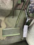
20250216-231134-016.jpg

For this one, I'm going to need to get out some new brushes for scrubbing.
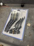
20250426-113715-001.jpg

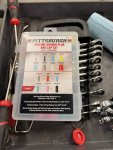
I'm also going to need a set of metric flare nut wrenches.
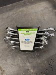
20250426-113726-003.jpg

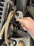
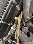
The hydro boost unit bolts directly to the firewall, sitting behind the brake master cylinder. The first step then, is to get the brake master cylinder out of the way.
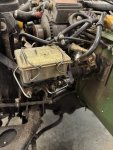
20250426-114420-004.jpg

The master cylinder only has two nuts holding it onto studs at the hydro boost unit; one is on the left (outboard) and one on the right (inboard). Both have some hardware attached, so it will take a few extra steps to remove.

First, this bracket goes from the master cylinder to the left splash shield and will need to be removed, as the nut you need to access is underneath. In my case, I had already removed the splash shield, so this was no big deal.
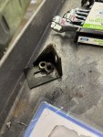
20250426-114502-005.jpg

15mm seems like a good place to start.
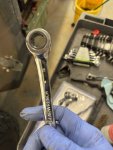
20250426-114903-006.jpg

With the splash shield bracket removed, the outboard (left) master brake cylinder nut can be removed from the stud on the hydro boost unit.
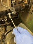
20250426-114912-007.jpg

Second, on the inner (right) side, remove the nut and washer holding the proportioning valve in place. The nut you need to access to remove the master cylinder is also underneath on this other side.
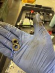
20250426-115051-008.jpg

Once it's loose, gently move the proportioning valve out of the way. In my case, it didn't need to be disconnected.
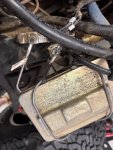
20250426-115537-009.jpg

With the proportioning valve out of the way, the inboard (right) master cylinder nut can be removed from its stud on the hydro boost unit.

Once loose, the entire master cylinder can be moved to the side. In my case, there was plenty of length in the brake lines to do this without pinching or bending anything. Since we didn't remove any brake lines, the brake system shouldn't need to be bled afterwards either. Added bonus.
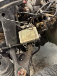
20250426-120035-010.jpg

Keep track of the hoses, and which ones are supposed to go where. I'm replacing these hoses at this same time, so I'm not super-concerned with dirt, but otherwise I would be.
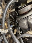
20250426-120527-011.jpg

There should be two high-pressure hoses, and one low pressure return hose. Of the high-pressure hoses, the outboard one goes to the steering gear; the inboard one, and the low-pressure hose, both go to the power steering pump.

I damaged the low-pressure hose getting it off, but again, I'm replacing all of these.
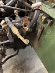
20250426-120905-012.jpg

A 19mm flare nut wrench will get the high-pressure hoses off without any damage.
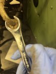
20250428-205812-013.jpg

Both high-pressure hoses will also have O-rings that will need to be replaced.
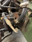
20250426-120921-013.jpg

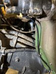
Finally, there is a small drain tube at the bottom of the hydro boost unit. This isn't shown in the TM -20; this is actually a leftover group 3305 part for the DWF kit. Just remember it's there before yanking out the unit.
20250428-110305-001.jpg

Here's the same picture, only cleaner with better lighting.
20250428-110627-002.jpg

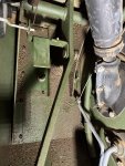
Inside the cabin, there are 4 nuts, with lock washers and flat washers, to remove the hydro boost unit.

The hydro boost pushrod is connected to the pedal with two washers and cotter pin. The outer washer is a 1/2" flat washer, while the inner washer is a 1/2" spring tension (wave) washer. I'm not quite sure at the moment how the later will be replaced.
20250428-111138-003.jpg

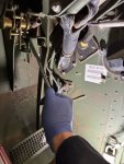
A long socket extension with a universal joint makes this pretty easy.
20250428-111152-004.jpg

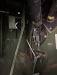
I don't remember what this picture was for, but obviously the entire unit is disconnected; make sure the hydro boost unit doesn't fall out once the fasteners are removed. You might want someone to hold it on the opposite side.
20250428-121003-005.jpg

Again, don't forget to remove the drain hose.
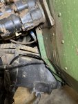
20250428-121009-006.jpg

Here's the old unit. Still leaking, even while it's sitting on a table...
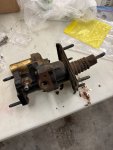
20250428-122319-007.jpg

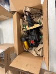
Here's the new one.
20250426-121010-015.jpg

We'll save what happens next for another post, probably later today.
 
Last edited:

mrandig

Active member
Steel Soldiers Supporter
125
146
43
Location
Houston, TX
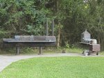
I had originally tried to enlist some help and moral support with BBQ, but didn't get any takers.
20250413-191233-032.jpg

How about a seafood boil? There were more shrimp, but the kids got 'em. The "slap" level was only medium, but Momma said it was too spicy this time. This is what's still left after days of eating. I can always make more.
IMG_3353.jpg
 
Last edited:

mrandig

Active member
Steel Soldiers Supporter
125
146
43
Location
Houston, TX
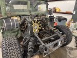
I decided this morning to take out the cooling stack before going any further. This needed to happen regardless, and if I'm starting to replace hoses, it would just be easier with everything out of the way. I'll come back to the hydro boost unit in just a while.

The unbolting of the power steering cooler was in an earlier post, so after taking two loosely held, previously stripped, bolts off, I was done. The transmission and oil cooler took a little bit longer.

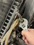
For the oil cooler side, the largest wrench I have is a 24mm, which wasn't going to be enough. Fortunately, a pair of crescent wrenches did the trick.
20250429-081103-001.jpg

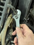
The ends on the oil cooler side don't turn, so you'll break something if you try too hard. Hold the fitting on the cooler side. Turn the fitting on the hose side.
20250429-081113-002.jpg

It will drip oil. So, keep some rags or whatever handy.
20250429-081126-003.jpg

The other side of the cooler is for the transmission fluid. This is just 5/8" low-pressure hose with some clamps. Nothing special.

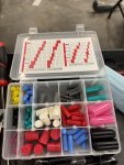
A box of plugs and caps from Harbor Freight is useful here.
20250429-082329-004.jpg

The Harbor Freight kit has plenty of types and sizes. I used either the grey or white plugs, and either the green or blue caps, depending on the line size. My eyes are too old to read the included chart; I just used the ones that fit best.
20250429-082337-005.jpg

20250429-082354-007.jpg

20250429-082402-008.jpg

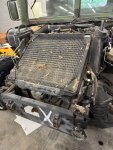
Power steering cooler is out; transmission and oil cooler are now out; last to go is the radiator. Thankfully, there were no more stripped bolts to deal with. As an added bonus, I also found two wrenches I had been missing.
20250429-170020-013.jpg
 
Last edited:

mrandig

Active member
Steel Soldiers Supporter
125
146
43
Location
Houston, TX
I wasn't planning on writing about radiator combs this morning, but here we are.

This first item is actually an alternative to radiator combs. This works for me; your results may vary. Radiator combs don't work great if there's heavy damage.

Here's a plastic tool for interior trim. I don't remember how expensive it was, but I don't think it was very much. I know I bought a full set of these back in the day at O'Rielly's Auto for maybe $25?
View attachment 943305

The nice thing about this tool is that it is tapered and longer than most combs from Amazon or the local parts place. It only does one row at a time, but it does a good job. Obviously don't use the wide face; use the narrow side.

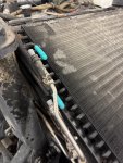
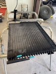
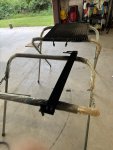
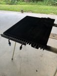
Below are some pics of today's battle with my transmission cooler. It was beat like it had owed someone money at some point. I'm not done yet, and there's still some additional straightening needed in spots, but good enough for now. There are some areas here that are so bad they're not going to be fixable.

Before:
View attachment 943306

After:
View attachment 943307

Before:
View attachment 943309

After:
View attachment 943310

Full view after <1 hour's work:
View attachment 943311

The blades may be straightened at this point, but unless you've got a steady hand and a good eye, they likely won't be perfectly parallel. Now if you wanted to go a step further and get a fin comb involved, it's a lot easier.
View attachment 943788

The correct comb is #10, at least it is for my HMMWV. This number refers to 10 fins per inch.

Depending on the brand, I've seen this particular type go for anywhere between $10-$25.
View attachment 943791

With a comb, things are starting to look even better; all of the fins are straight and aligned.
View attachment 943789

This method also works great on the power steering cooler. In this case, there is some damage on the lower part that I can't fix, because the fins are too far gone. By "gone" I mean they're torn out.
View attachment 943790

The radiator should be getting replaced sometime over the next few days, so I'm not so worried about that.

Until next time, friends!
I was rambling on a few weeks ago about radiator combs, and cooling fins being straight, etc. I'm sure at least a few people stopped reading this thread at that point.

Here's where the story comes together.

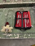
Essential tools.
20250429-170402-014.jpg

I was also using an automotive trim tool, but I was too lazy to find it for this picture.

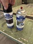
Paint prep and specialty radiator paint.
20250429-170002-012.jpg

Almost ready for refinishing.
20250429-164247-011.jpg

Power steering cooler is done.
20250429-164233-010.jpg

It's hard to see, but it does look amazing. Perfectly straight, totally clean, just like new in satin black.

Transmission and oil cooler is next up.
 
Last edited:
mrandig

Active member
Steel Soldiers Supporter
125
146
43
Location
Houston, TX
Transmission and oil cooler completed.

Now I just have to find somewhere to keep everything safe until it's time to put it all back together.
20250430-120252-001.jpg
 
Last edited:
mrandig

Active member
Steel Soldiers Supporter
125
146
43
Location
Houston, TX
If I was going to make a post on how to remove the radiator in a M1123, I missed my opportunity. Once I got rolling, any chance of taking pictures went out the window.

Let's just say it takes at least two people and will probably involve a bit of cussing.

At least it's out.
20250430-154320-006.jpg
 
Last edited:

mrandig

Active member
Steel Soldiers Supporter
125
146
43
Location
Houston, TX
Now that I'm into the guts of this thing, I think I'm going to need a bigger parts order. There are more and more things that should be replaced just while I'm in the neighborhood.

I'm also going to need some spray paint for touch-ups. I'm assuming the paint on the frame is the same CARC as the body. I will need to look around the site, as I've seen this information a few different times; I'm just too tired to do it tonight.
 

mrandig

Active member
Steel Soldiers Supporter
125
146
43
Location
Houston, TX
Here we go...

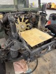
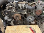
A 24"x24" sheet of 3/4" plywood should make for a good, flat workspace.
20250503-085903-001.jpg

We'll remove in order, then replace as needed; re-installation would then be in reverse.

1. Fan (ok)
2. Serpentine Belt (replace)
3. Water pump pulley (ok)
4. Oil filter tube (replace O-ring only)
5. Thermostat bypass hose (replace)
6. Tensioner (replace), idler pulleys (replace) and backing plate (ok)
7. Power steering pump (replace)
8. Water pump (replace)

I think that's the plan for today. Seems like everything could be done in one day, but with this truck, nothing ever goes to plan...
 
Last edited:
mrandig

Active member
Steel Soldiers Supporter
125
146
43
Location
Houston, TX
Before I get started, anybody know the story here?

For the removal of the fan drive and fan blade, there's a note that in the TM-20 (3-78 ) that says, "mark position of fan blade for installation".
1746287753093.png

Am I marking the fan position relative to the water pump pulley it attaches to? To its position when it was removed? To the fan drive?

Is this to address an assembly issue? Is this a balance issue?

Not quite sure what I'm accomplishing here. This is for a water pump replacement, so it's all going to come out.
 
Last edited:
TNDRIVER

Well-known member
Steel Soldiers Supporter
356
557
93
Location
Cleveland,TN
I believe this is to access the bolts be
Before I get started, anybody know the story here?

For the removal of the fan drive and fan blade, there's a note that in the TM-20 (3-78) that says, "mark position of fan blade for installation".
View attachment 945877

I believe this is to access the bolts behind the clutch.................................................. I believe
 

mrandig

Active member
Steel Soldiers Supporter
125
146
43
Location
Houston, TX
Fan removal

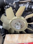
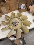
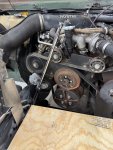
To remove the fan blade and fan drive, there's a total of 4 socket head cap screws that will need to be removed.
20250503-144514-002.jpg

In my case, these needed a 5/16" Allen key.
20250503-144525-003.jpg

While I try not to get too happy with the impact wrench, I was having trouble with the fan spinning in place.

Brrrr. Brrrr. Brrr. Done.
20250503-144936-004.jpg

After a few minutes, and a little wiggling, the fan is out.
20250503-144943-005.jpg


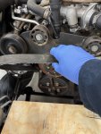
Serpentine belt removal

With the fan removed, next up is removing the serpentine belt.
20250503-145025-006.jpg

A 3/8 adapter installed on a breaker bar.

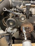
Rotate the tensioner (bottom left) clockwise. It will pull down and away; the serpentine belt will then have enough slack to remove.
20250503-145052-007.jpg

Serpentine belt removed.
20250503-145107-008.jpg
 
Last edited:
mrandig

Active member
Steel Soldiers Supporter
125
146
43
Location
Houston, TX
Water pump pulley removal

While the previous cap screws were SAE, I guess now we're doing metric. I can never keep track.

In my case, the screws were all 6mm.
20250503-150251-011.jpg

Brrrr. Brrrr. Brrr. Done
20250503-150602-013.jpg

As I was removing the water pump pulley, I happened to notice a "red" mark going vertically, and another "red" marking running horizontally. I'm going to guess these are related to the proper positioning of the fan; we'll see upon re-installation.

As expected, the water pump is bad. Sounds and feels like it's full of gravel inside. It's horrible.
20250503-150710-014.jpg


Tensioner Removal

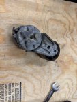
My tensioner was held in place with a 13mm bolt, which threads directly into the mounting plate. It's held in alignment by a tab that's at the rear.
20250503-150328-012.jpg


Idler pulley removal

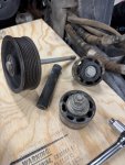
For the smaller idler pulleys, we had a 3/4" nut, with a 15mm bolt.
20250503-145531-009.jpg

Note the large bolt and large spacer for the big pulley. This last one goes through the mounting plate and directly into the right cylinder head.
20250503-145910-010.jpg


Mounting plate removal

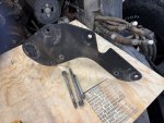
Finally, the mounting plate for the tensioner and idler pulleys need to be removed. Not much to say, as once everything else is removed, there's three more bolts.

Each is a different size and length, so keep track during disassembly. The two longer bolts also secure the water pump, and since they thread into a water passage, they will need sealant.

Going clockwise from bottom, I think we had 15mm, 16mm and 13mm. I'll double check and edit this post later if I'm incorrect.
20250503-151014-015.jpg
 
Last edited:
mrandig

Active member
Steel Soldiers Supporter
125
146
43
Location
Houston, TX
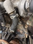
Now we're getting closer to removing what we're really here for. We still need to get the thermostat bypass hose out, and the oil filler tube. There's also a section of heater hose, that doesn't even have clamps on it; we'll just wiggle that out while were in here also.
20250503-151022-016.jpg


Thermostat bypass hose removal

There are two clamps on the bypass hose, one upper and one lower. A pair of channel locks or pliers can be used to remove the tension, then just slide the clamps out of the way. Give the hose a twist to break it loose, and then pull...
20250503-151231-017.jpg


Oil filter tube removal

The oil filter tube is held in place with two nuts, which are attached to two studs securing the backing plate for the water pump. These are 15mm also, and once removed, the oil filter tube can be pulled away.
20250503-151526-018.jpg

Also, don't forget to remove the hose which runs from the oil filler tube over to the CDR/PCV valve. This can just be laid out of the way for the time being.
20250503-151755-019.jpg

Finally, there's an O-ring where the filler tube inserts into the backing plate, which then leads to the cranckcase. More than likely, this will need to be replaced. Mine did.
20250503-151908-020.jpg

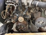
Here's everything removed. I'm taking a break at this point but should be back shortly.
20250503-151912-021.jpg
 
Last edited:
mrandig

Active member
Steel Soldiers Supporter
125
146
43
Location
Houston, TX
Water pump removal

There's a total of 13 bolts that will need to be removed, 3 of which have already been taken out at this point. There are a few different types of bolts, as well as studs, that are involved.

4 large bolts and 1 stud thread into the block at the water passages (4 & 8 o'clock); 2 small bolts thread into the crankcase (5 & 7 o'clock); and 4 short bolts (9,10,2,3 o'clock) and 2 studs (11 & 1 o'clock) mount the assembly to the block.
20250503-151944-022.jpg

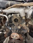
Here's another picture with everything removed. Seeing where things go helps me understand what fasteners go in which spots, as well as which ones need thread sealant, etc.
20250503-200422-026.jpg

There's still going to be some water (coolant) left in the block, so just be prepared for a spill. Fortunately, this pump isn't as heavy as it could be, so I was able to do the removal without needing any extra hands.

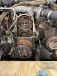
I don't know if I'm going to try to get the new pump installed tonight but it is definitely a project for tomorrow.


Power steering pump removal (1)

Last but not least is the power steering pump. I should have quit while I was ahead.

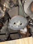
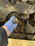
The power steering pump actually bolts onto a "U" shaped bracket, and you should be able to un-bolt, pull up, and then out to remove. I was feeling a little challenged getting to these fasteners, so I decided to see if I could do better with the pulley removed.

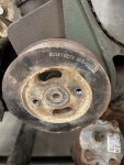
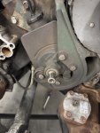
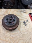
The first piece is actually a cover. The two outside bolts secure the cover; the center bolt also secures the pulley to the pump. Once removed, the pulley is still installed and isn't going anywhere soon.
20250503-193315-023.jpg

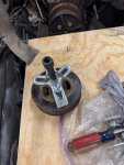
I do have a puller that should work for removing this, but I don't have the correct hardware (bolts).
20250503-194830-024.jpg

I really just can't wait. I bet installation on the new pump is going to be a blast also.
20250503-194943-025.jpg

So, with the pulley still installed at this point, I'm faced with a decision. Do I remove the entire assembly, and try to tackle this pulley on my workbench, or do I wait until the pulley is off to remove the assembly?
 
Last edited:
Sgt Jiggins

Potato Peeler
Steel Soldiers Supporter
481
279
63
Location
NorCal
As you mentioned earlier, the radiator... that was the worst of it really. There's plenty of room to work once that's out. I'm trying to think back to when I did the pulley. None of it really sticks out in my mind as being all that terrible.

One thing you might consider, especially given your latitude, is deletion of the cadillac valve on the fan. I did that and replaced the plastic fan with a (slightly smaller) metal unit. I went this route after seeing the carnage under the hood from prior belt failure which lead to the plastic fan grenading. Plus it made for a simple(r) system.

Good luck!
 

mrandig

Active member
Steel Soldiers Supporter
125
146
43
Location
Houston, TX
Power steering pump pulley removal

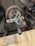
So, after last night, I gave the issue some thought and decided that there was no justifiable reason whatever that a harmonic balancer puller shouldn't work to get the power steering pump pulley off.

My power steering pulley (RSK18218 ) doesn't have a raised lip at the bolt, so there was no way to use most of the "standard" power steering pulley removers sold in stores. There's just nothing for a puller to grab onto.

A pair of new bolts from Home Depot went onto the balancer puller, and everything fit just fine; now we'll have to see how it holds up in use. It may strip; it may slip; an unexpected "pop" is always fun also.

I used the largest screwdriver I had just to keep things from spinning as I worked.
20250504-151735-001.jpg

Turned out, that removing the pulley this way was surprisingly non-eventful. It took a minute, and I swore that I was going to bend my screwdriver, but it did come out peacefully at the end.
20250504-152013-002.jpg

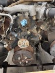
Now we can get back to what we were doing. My job of removing the power steering pump just became that much easier.
20250504-152021-003.jpg

Once this pump is out, that's about it; we're officially at the putting-back-together part of the project.
 
Last edited:
mrandig

Active member
Steel Soldiers Supporter
125
146
43
Location
Houston, TX
Before going any further, a bit of clean-up is in order. A clean workplace is a happy workplace:)

I think it's a good practice to stop periodically, inventory and put all of the tools away, and make sure everything is cleaned like it was starting Day 1. This even includes sweeping and usually moping the floors. For a truck that came to me this dirty, it's a necessity.

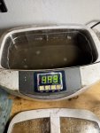
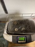
For the parts, everything that fits goes into the ultrasonic cleaner.
20250428-135422-008.jpg

As I mentioned earlier, this works great for most fasteners.
20250428-140200-009.jpg

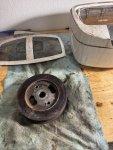
Even the power steering pump pulley looks much better. Turns out, this is as large as I could go, so anything bigger would need to be cleaned another way.
20250504-162326-004.jpg

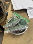
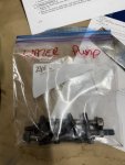
Once out of the cleaner, everything gets bagged and tagged for re-installation.
20250504-162639-007.jpg

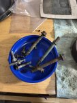
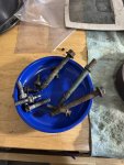
The water pump bolts however, are going to be a different story. They are super gummed up with sealant and other types of nastiness.
20250504-162332-005.jpg

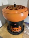
For the water pump bolts we'll try the tumbler. This is full of abrasive media, and the parts are then, "tumbled". We'll see shortly if this works. If not, we have a few other options. I'll probably leave them for 1-2 hours at least.
20250504-162347-006.jpg

I'm actually starting to wonder if I need to chase some of the threads the bolts go into also. If these bolts are this nasty, the bolt holes can't be much better.

Worst case, if the tumbler doesn't work, we'll break out the bench grinder and hit these with a wire wheel.
 
Last edited:
mrandig

Active member
Steel Soldiers Supporter
125
146
43
Location
Houston, TX
I know taking each bolt off, cleaning it, bagging, and the tagging it is pretty over the top for some, but there's really no comparison.

It's a bit of extra work, but I think it's worth it. Not only is it just cleaner, but it's also more organized, and it's a good opportunity to inspect everything before putting it back on.

I end up losing very few pieces this way. This is important when half the truck is disassembled and sitting on the workbench.

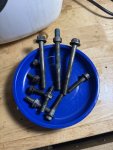
Before:
20250504-162332-005.jpg

After:
20250504-190613-008.jpg

Until needed:
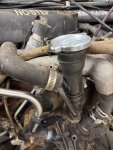
20250504-191435-009.jpg
 
Last edited:
mrandig

Active member
Steel Soldiers Supporter
125
146
43
Location
Houston, TX
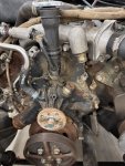
While the parts are soaking, the floors are drying, etc. I'm just going to clean up a few parts on the truck, including gasket mating surfaces, and hose connections. I've still got to replace the high and low pressure hoses as I go.

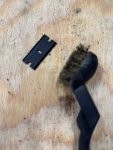
A trusty brass brush and some carburetor cleaner is always useful. For the gasket surfaces, I'm using "plastic" razor blades, because why the hell not?
20250504-200214-011.jpg

They're kind of like safety scissors. I guess if you live in an area where knife-crime is a concern, you'd want these?

They're not particularly good for anything else, but OK for removing old sealant.
20250504-200222-012.jpg

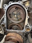
The rust on this gear drive makes me wonder what everything else looks like inside. That said, I'm willing to take a drive and find out.
 
Last edited:
Top