• Steel Soldiers now has a few new forums, read more about it at: New Munitions Forums!

  • Microsoft MSN, Live, Hotmail, Outlook email users may not be receiving emails. We are working to resolve this issue. Please add support@steelsoldiers.com to your trusted contacts.

Glo Plug Solenoid Help

flyfishtrailer

Well-known member
Steel Soldiers Supporter
554
1,041
93
Location
Cool, CA
I am writing this after dark and will add pictures tomorrow but hoping for some insight/help in the meantime. I decided to replace the glo plug solenoid (old black plastic one) as a precautionary measure as it had not failed yet. I purchased the Napa ST85 and within a few minutes had it changed out. I went to test the glo plugs (key turned to on) to see if we had 12 volts at the plugs. Glo plug light illuminated, but no power to the plugs. Checking at the new solenoid, red wire is constant hot, power from ignition causes both the pink and lt blue to register 12.3 volts, but the circuit out to the glow plugs has no power (orange wires). I tried changing the pink and lt blue wires thinking maybe I had them backwards. Same result. I read here that the ST85 is the proper replacement. What did I do wrong? Do I have a bad solenoid from Napa? I plan on taking the solenoid off and trying to test it. What should I look for? Thanks in advance
 

flyfishtrailer

Well-known member
Steel Soldiers Supporter
554
1,041
93
Location
Cool, CA
As I sit and pile through information and previous threads.......the ST85 is all metal. Does that mean it is grounding to the body? What have others done to remedy this since this appears to be commonly used replacement for CUCV's?
 

MarcusOReallyus

Well-known member
4,524
816
113
Location
Virginia
  1. You should NOT have 12v to both the pink and the blue wires. The blue wire provides ground to the relay coil when the GPs are activated.
  2. Some ST85s do ground through the case. Disconnect your unit and measure continuity from each of the terminals to the case. NONE of them should have continuity to the case.
 

flyfishtrailer

Well-known member
Steel Soldiers Supporter
554
1,041
93
Location
Cool, CA
  1. You should NOT have 12v to both the pink and the blue wires. The blue wire provides ground to the relay coil when the GPs are activated.
  2. Some ST85s do ground through the case. Disconnect your unit and measure continuity from each of the terminals to the case. NONE of them should have continuity to the case.
Marcus,

I checked that this morning. There is no continuity of the 4 terminals of the ST85 to the attachment plate of the ST85. I just pulled an ugly mess of glow plug wiring harness that one of the PO's put in (for which we can't figure out why as the factory harness was still intact and just had the glow plug attachment leads cut off). I had to add pigtails to the original harness to connect to the glow plugs, but that is all good now. Checked them and they are all connected. The solenoid (109 as seen in the picture) that was in the truck when I got it had bypassed the original glow plug system (glow plug card) and was activated by a push button in the cab. The Napa 109 had the pink wire attached, but only the red wire, the glow plug harness they put in, and the wire from the button. Th unit grounds to the truck (we verified that with continuity test). The TM tells us to replace the solenoid and or the glo plug card. I have one of the glo plug cards (brand new and just installed) from Hillbilly Wizard that have the LED lights to aid in seeing the functions.

Yesterday, before I decided to change the solenoid to the ST85, we disabled the push button, hooked the lt blue, pink, small orange, the red and the harness connections from the PO. The system worked. What we found was that the solenoid remained closed and that power to the GP's was continuous and never opened the circuit to shut the glo plugs off. When the key is off, there is only power to the red wire side of the solenoid as there should be. With the ST*% installed (not grounded to the truck like the 109), the circuit remained open and would never active. Checking the pink, lt blue and red all carried power. It seems we are not getting the - relay from the lt blue wire or the ST85 would work perfectly. What am I missing?

IMG_9218.jpg
The above is the GP harness that the PO put in to bypass the system

IMG_9219.jpg
This is a picture of how it was set up yesterday when we first put it all back together like it should have been and before we realized the circuit wouldn't close
 

MarcusOReallyus

Well-known member
4,524
816
113
Location
Virginia
Checking the pink, lt blue and red all carried power. It seems we are not getting the - relay from the lt blue wire or the ST85 would work perfectly.

Okay, sounds good. Now, are you checking for power when the wires are connected? If so, it makes sense that the blue wire would show 12v. That's because it's connected through the coil to the small red (pink) wire, and when the GPs are not activated, its other end is connected to nothing. So, put 12v on the pink and the blue gets 12v, too.

So, if you disconnect the two small wires (red and blue) going to the small terminals on the relay, you should see 12v on the red when the key is on. The blue should show nothing. No ground, no jolts, nothing.

When the GP card wants to tell the relay to activate the GPs, it will provide ground to that blue wire, which completes the circuit through the coil, and activates the relay.

So, if that's not happening, either the ground for the GP card is not good, or some other component is not telling the GP to do its thing. There's a temp sensor that can affect this. If the sensor is bad, the GP card won't provide that ground.

Before we go looking for temp sensor problems, check for continuity on the blue wire to the GP controller, and check the ground on the GP controller. The grounding point is a 6 prong connector up under the dash either on or very near the parking brake assembly.

See here for a picture of it.

You need to verify that the blue wire does connect to the GP controller, and that the GP controller has a good ground connection.

What am I missing?

Just like the rest of us, you are missing the basic common sense that would tell you to sell this thing and get a sensible truck! :D

(y)
 

flyfishtrailer

Well-known member
Steel Soldiers Supporter
554
1,041
93
Location
Cool, CA
Okay, sounds good. Now, are you checking for power when the wires are connected? If so, it makes sense that the blue wire would show 12v. That's because it's connected through the coil to the small red (pink) wire, and when the GPs are not activated, its other end is connected to nothing. So, put 12v on the pink and the blue gets 12v, too.

So, if you disconnect the two small wires (red and blue) going to the small terminals on the relay, you should see 12v on the red when the key is on. The blue should show nothing. No ground, no jolts, nothing.

When the GP card wants to tell the relay to activate the GPs, it will provide ground to that blue wire, which completes the circuit through the coil, and activates the relay.

So, if that's not happening, either the ground for the GP card is not good, or some other component is not telling the GP to do its thing. There's a temp sensor that can affect this. If the sensor is bad, the GP card won't provide that ground.

Before we go looking for temp sensor problems, check for continuity on the blue wire to the GP controller, and check the ground on the GP controller. The grounding point is a 6 prong connector up under the dash either on or very near the parking brake assembly.

See here for a picture of it.

You need to verify that the blue wire does connect to the GP controller, and that the GP controller has a good ground connection.


Just like the rest of us, you are missing the basic common sense that would tell you to sell this thing and get a sensible truck! :D

(y)

Marcus,

I will check all of the continuity checks you listed in the morning when I can see. This has been such a pain in my A-- that i ready your reply and went and checked for the 6 prong grounding post. There is nothing attached to any of the 6 prongs, only the one wire that is attached to the screw holding it onto the sheet metal of the truck. camera flashlight not bright enough to do any more recon for black wires tonight. Should there be additional (GP card) wires coming off that?
 

MarcusOReallyus

Well-known member
4,524
816
113
Location
Virginia
. There is nothing attached to any of the 6 prongs, only the one wire that is attached to the screw holding it onto the sheet metal of the truck. camera flashlight not bright enough to do any more recon for black wires tonight. Should there be additional (GP card) wires coming off that?
Nope. That one ground wire is for everything inside the truck. Not a good design.

It's probably okay, but it won't hurt to take it apart and hit it with a wire brush or sandpaper. Make some nice shiny metal, add some dielectric grease to prevent corrosion, and put it back.
 

Squibbly

Well-known member
408
1,039
93
Location
Alabama
This is the relay I bought because the PO put the incorrect relay in it (of course).
Amazon.com: HVACSTAR Military Vehicle Army Marine 5/4 ton M1008 M1009 M1028 CUCV Glow Plug Solenoid : Automotive

That being said, are you saying that if you disconnect that blue wire from the solenoid, and check power to it (with or without key in run position), that you see power to it when you turn the key? If that is the case, that is wrong.
That blue wire is ground. That's it. It is either grounded or not grounded.

That is how the glow plug module activates the relay, it simply closes a switch to ground the blue wire and complete the circuit to close the relay (using the pink and black wire) and let power flow from the red wire off the firewall, to the orange wires.

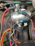
Here is my relay (Don't laugh...you should have seen it when I got it. I'll be cleaning it up). 😂

I still have the resistor pack working, so that top red wire is coming off the resistor pack.

The next one down is the pink and black wire, which is 12v when you turn the key.

The next one down is the light blue wire, which is grounded by the GP module when the temp isn't to the right temperature. Ignore the black wire. That is my push button override. I don't have the GP module installed in my truck. I like pushing the button, I don't live in a freezing climate, and nobody uses my truck. If I need to lend it to an idiot, I'll put the card I recently fixed back in it.

The orange goes to the GPs.

1641149796124.jpeg

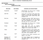
You can check that everything is doing what it is supposed to be doing by following the TM for testing the glow plug system.
1641150287786.png

I went through most of this in a video for another forum member who asked how to use a multimeter.

My brother @Rocknus went through a much longer video for his glow plug issues, if you would like to watch a less sucky video than the one above.

I don't know if this troubleshooting guide is on this forum someplace, but this one I found out on radionerds that has the glow plug module workflow is pretty good.
CUCV_Glow_Plug_System_Diagnosis_and_Troubleshooting.pdf (radionerds.com)
 
Last edited:

MarcusOReallyus

Well-known member
4,524
816
113
Location
Virginia
That blue wire is ground. That's it. It is either grounded or not grounded.

Well, that depends. If it's connected to the relay (solenoid), it has 4 possible conditions:


  1. The ignition key is OFF, and the GP card is NOT providing ground to activate the GPs.
  2. The ignition key is OFF, and the GP card IS providing ground to activate the GPs.
  3. The ignition key is ON, and the GP card is NOT providing ground to activate the GPs.
  4. The ignition key is ON, and the GP card IS providing ground to activate the GPs.

#1 is a normal condition, and isn't a problem, so we can ignore it for now.

# 2 should not happen, and if it does, that's a different problem than we are discussing, so we can ignore it for now.

# 3 is a normal condition and you will see 12v at the blue wire connection to the relay.

#4 is a normal condition and will show ground at the blue wire connection to the relay.


Here's why #3 will show 12v at the blue wire connected to the relay: The other end (at the GP) is not connected to ground (or anything else), but it IS connected to the small red (pink) wire through the relay's coil. With no connection to ground, there is zero current flowing through the coil, so the resistance of the coil does not drop any voltage, so you will see the full 12v at the other terminal where the blue wire lives.

It's exactly the same thing as when you see 24v at the top of the GP relay when the GPs are not activated (assuming the GP resistor is NOT bypassed). Where there is no current flow across a resistor, there is no voltage drop.

Now, if he's taking that voltage measurement at the blue wire with it NOT connected to the relay, somethin' ain't right.
 

Squibbly

Well-known member
408
1,039
93
Location
Alabama
Now, if he's taking that voltage measurement at the blue wire with it NOT connected to the relay, somethin' ain't right.
Agreed. Sorry if that wasn't clear.

The PO of my truck had the wrong solenoid in the truck, and had a toggle hooked into the fuse box and the other side of the toggle to a small post on the solenoid. There was nothing on the other post. I'm not even sure how it was working, unless it was an "always on" relay, which would explain why there were zero working GPs in the truck and had clearly gotten hot enough to swell at the tips and have slag on them. So while the toggle got the relay to "click", it was in effect doing absolutely nothing, besides perhaps burning up GPs.
 

flyfishtrailer

Well-known member
Steel Soldiers Supporter
554
1,041
93
Location
Cool, CA
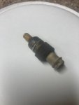
So we just got done checking continuity to all of the glow plug wires (Including the temp sensor) and all are good. we just pulled the temp sensor out and will be checking it to (and probably replacing it as they have one at the auto parts store, we are heading to for some maintenance items for my jeep. We pulled it out and it definitely looks like the original GM part. If this is bad, will it no allow the blue wire to ground?


IMG_9221.jpg
 

flyfishtrailer

Well-known member
Steel Soldiers Supporter
554
1,041
93
Location
Cool, CA
Sorry about the delay, I had to drive to Oregon to pick my son up from Winter Encampment. While I was gone, my stepson went through all of the tests in the TM. All of the wiring checked out. The solenoid and temp sensor were replaced, all tests indicate the GP card is the issue (which was new). When testing the card, the green light would come on when the key was turned, the amber light would come on when the Wait light was on, but never got the red light indicating the ground signal going to the solenoid to activate the GP harness to heat the GP's when the wait light went off.

He discovered the original issue that probably fried the original GP card. The 24-volt wire coming over from the 24-volt bus bar had been cut off (with the resister still on it). Checking the voltage on the other side of it, there was 24 volts, so the resister (reducer?) had gone bad and supplied 24 volts which probably fried the card and the solenoid. The PO then created a whole new GP system (including a new harness for the GP's) for a push button to heat the GP's. We now use the push button to send the ground signal. I will follow up with the place I bought the GP card and see about getting it replaced.

Thanks to everyone that posted here. I am leaning a great deal about diagnosing/troubleshooting and repairing this truck ( I have never had a shop class in my life). I will post the outcome once a new glo plug card is installed.
 

MarcusOReallyus

Well-known member
4,524
816
113
Location
Virginia
He discovered the original issue that probably fried the original GP card. The 24-volt wire coming over from the 24-volt bus bar had been cut off (with the resister still on it). Checking the voltage on the other side of it, there was 24 volts, so the resister (reducer?) had gone bad and supplied 24 volts which probably fried the card and the solenoid.

Not quite sure what you are describing, but note this: With the stock GP resistor in place, you WILL measure 24v at the top of the GP relay when the GPs are not engaged (turned on). This is normal.

When the GPs are engaged (turned on), you should see 12v at the top of the GP relay.

This has nothing to do with the GP controller card, which should never see 24v under any conditions.

Even if you bypassed the resistor, and fed 24v straight to the top of the GP relay, it shouldn't bother your GP controller. It would just burn up your GPs pretty quickly.
 

Squibbly

Well-known member
408
1,039
93
Location
Alabama
Not quite sure what you are describing, but note this: With the stock GP resistor in place, you WILL measure 24v at the top of the GP relay when the GPs are not engaged (turned on). This is normal.

When the GPs are engaged (turned on), you should see 12v at the top of the GP relay.

This has nothing to do with the GP controller card, which should never see 24v under any conditions.

Even if you bypassed the resistor, and fed 24v straight to the top of the GP relay, it shouldn't bother your GP controller. It would just burn up your GPs pretty quickly.
True.

If you stick a multi-meter set to 200V DC on the top of your GP relay, you'll see 24-25V. As soon as the relay is activated, you'll see the voltage drop to 9.2 then gradually increase as the plugs heat up to 12ish range.
 

flyfishtrailer

Well-known member
Steel Soldiers Supporter
554
1,041
93
Location
Cool, CA
UPDATE: I contacted Hillbilly Wizard regarding the GP card. They said to send it back and they would test it and replace if needed. I heard back from them yesterday and they said the card was not working properly and a new one was sent out. I will update again once it arrives.
 

sgms18

Active member
Steel Soldiers Supporter
241
85
28
Location
North Augusta SC
Watching the above video I noticed my glow plug relay is wired opposite of his. My pink, key on 12v wire is on the bottom terminal & the blue, ground is on the top. It's working they way it is. Does it matter which way it's wired?
 

MarcusOReallyus

Well-known member
4,524
816
113
Location
Virginia
Watching the above video I noticed my glow plug relay is wired opposite of his. My pink, key on 12v wire is on the bottom terminal & the blue, ground is on the top. It's working they way it is. Does it matter which way it's wired?

Nope. Pink and blue on opposite small terminals = good to go. Top or bottom does not matter.
 

flyfishtrailer

Well-known member
Steel Soldiers Supporter
554
1,041
93
Location
Cool, CA
UPDATE: So i received my new replacement GP module (card) today. Popped it in and turned the key...green light, amber light and red light! We now have a fully functioning as original GP system in the truck. Super Happy! Thanks to John at Hillbilly Wizard....great customer service and super-fast turnaround. Also, thanks for all of YOUR advice, suggestions and wisdom Marcus and Squibbly
 
Top
AdBlock Detected

We get it, advertisements are annoying!

Sure, ad-blocking software does a great job at blocking ads, but it also blocks useful features of our website like our supporting vendors. Their ads help keep Steel Soldiers going. Please consider disabling your ad blockers for the site. Thanks!

I've Disabled AdBlock
No Thanks