• Steel Soldiers now has a few new forums, read more about it at: New Munitions Forums!

  • Microsoft MSN, Live, Hotmail, Outlook email users may not be receiving emails. We are working to resolve this issue. Please add support@steelsoldiers.com to your trusted contacts.

Glow plug card

cucvrus

Well-known member
11,473
10,427
113
Location
Jonestown Pennsylvania
Is there such an animal as a CUCV with unmolested wiring? Rick?
If I am the Rick you are referring to. I hope to tell you man. I have a few and sold a few. I may have added a few lights but I kept the original harness and have not hacked one yet. Un hacked a many jacked up harnesses and saved a few CUCV's from inevitable doom. Now I am down to my last 3. I am NOT looking for any more. Have a Great Day.
 

Sharecropper

Well-known member
Steel Soldiers Supporter
1,836
987
113
Location
Paris KY
If I am the Rick you are referring to. I hope to tell you man. I have a few and sold a few. I may have added a few lights but I kept the original harness and have not hacked one yet. Un hacked a many jacked up harnesses and saved a few CUCV's from inevitable doom. Now I am down to my last 3. I am NOT looking for any more. Have a Great Day.
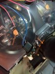
Richard; Just sent you a PM.
 

Oerthedge21

Member
250
20
18
Location
Northford CT
I know this thread is a little old, don't know if anyone still sees it, but I got my new gp harness and relay today. Only cost me 100$ for both of them, as compared to over 120$ on eBay just for the harness. Gonna try to install it today, seems easy enough but who knows. IMG_20180913_162123468.jpg
 

Oerthedge21

Member
250
20
18
Location
Northford CT
New glow plug harness, new issues

Some of you may remember me from the glow plug card thread not long ago in which we discovered that somebody had totally remived the gp card from my 1010. Well I bought a fresh gp harness and soleniod and wired it as per the wiring diagram in my TM. The card (aftermarket) has a post for a ground wire for the addition of a manual gp button without hacking wires. I did install a button for a backup with the new system. So here's the issue. The card doesn't seem to want to light the plugs. The button will click the relay and send power to them, but the card has yet to do so. More troubling though, is the fact that the dark blue with that runs to the WTS light from the card gets continuos power once the key is on, even though the GPs aren't getting power without the button pushed. Anyone have any idea what might be happening? Let me know if you need any more info on what's going on, I'd like to get this resolved soon. IMG_20180913_182632220_LL.jpgIMG_20180913_182700556_LL.jpg
 

cucvrus

Well-known member
11,473
10,427
113
Location
Jonestown Pennsylvania
I have never seen wiring like that on a glow plug solenoid. How does the relay get power? Does that blue wire run to the wait light in the dash? What about the hot wire to the top of the solenoid? And has this been converted to 12 volt? Hot Rodding and modification may be able to assist. Good Luck. The TM's don't show that as the correct way to wire the glow plug system. Trying to help but am baffled by the set up.
 

joshuak

Active member
747
214
43
Location
Slower shore, DE
Last edited:

Oerthedge21

Member
250
20
18
Location
Northford CT
Yes the truck is 12v now, that blue wire that goes to the large top post is a 12v feed from the junction block on the firewall, it was already there as a power for the previous setup so I just reused it instead of making a while new wire from the buss bar on the pass side of the firewall. I don't have any larger cable right now so I just did that as a temporary setup. The blue with at the wait light is getting constant power for some reason, for as long as the key is on. The pink black that runs to the wait light is also receiving constant power.
 

antennaclimber

Moderator
Moderator
Steel Soldiers Supporter
1,367
949
113
Location
State College, PA
In the photo of the relay, it appears there is a black wire going to the terminal with the orange wires. Where does that wire go? Is it connected to the Wait light? If so, it should not.

You will need to remove any and all additional wiring, splices or other hacks from the civilian controller modification. That means tracing out every wire from the new controller to every point it needs to be properly connected to. I think you have some mods still connected to the new controller that are hampering the functions.

I merged this thread so we have all of the information from the civi mods here as well.

This is the correct schematic for the GP system:
 

Attachments

Last edited:

Oerthedge21

Member
250
20
18
Location
Northford CT
That black wire was on there for voltage testing purposes so I could reach it while turnjng the key in cab (I was working alone) it does not attach to anything. I had removed all of the hacked working o could find. As I said, I bought a whole new harness, I didn't try to fix what was destroyed. However, the blue wire to the wait light isn't part of the gp harness so I have to trace it and make sure it hasn't been hacked apart, didn't get time to yesterday as it was getting late when I was finished with the install
 

Oerthedge21

Member
250
20
18
Location
Northford CT
Also, my wiring differs slightly in the power to the relay. Since the truck is 12v the resistors are gone so the wire just goes from power bar to relay
 

Oerthedge21

Member
250
20
18
Location
Northford CT
I'm getting power from both the pink black and the blue wire at the relay when I turn the key on, it's being supplied from the truck somewhere, not coming through the relay. I thought the blue wire was supposed to be a ground so why there's power to it I'm not sure
 

antennaclimber

Moderator
Moderator
Steel Soldiers Supporter
1,367
949
113
Location
State College, PA
I'm getting power from both the pink black and the blue wire at the relay when I turn the key on, it's being supplied from the truck somewhere, not coming through the relay. I thought the blue wire was supposed to be a ground so why there's power to it I'm not sure
Power on the Pink/black wire is normal. This powers the GP card and the relay.

The GP card sends a ground command on the Light Blue wire to the GP relay to close it. The Light Blue wire will have voltage on it (thru the coil of the relay) if the GP card is not sending a ground command to the relay. The Light Blue wire is not directly connected to ground. It gets ground from the GP card when the card gives the command to close the relay.

The Wait light gets +12 volts from the fuse box all the time on the Pink/black wire, the GP card sends a ground command to light it via the Dark Blue wire.

All the Orange wires should be on the bottom large terminal of the GP relay and the top large terminal should have +12 volts in your situation.

The Yellow wire to the GP card is from the temperature sensor on the engine.

The Black wire to the GP card is ground and the ground from the temperature sensor.
 

Oerthedge21

Member
250
20
18
Location
Northford CT
Thats exactly how I have it wired, must be the temp sensor because I don't think it's quite correct. The temp sensor is supposed to be in the pass side head right? Because it's currently using one that's in the pass side of the head but it's up on top instead of on the side like it is in most pics
 

antennaclimber

Moderator
Moderator
Steel Soldiers Supporter
1,367
949
113
Location
State College, PA
The sensor to the rear of the engine on the passenger side of the block is for the IP advance/high idle. It's actually a switch and not a thermister.

The GP sensor changes resistance value with temp.
 

Oerthedge21

Member
250
20
18
Location
Northford CT
So I'm getting constant power at the pink black wire to the wait light, but the blue with is also getting constant power, and the light doesn't come on when I hold the button for the glow plugs. I still have no self functionality of the card either, I believe it's due to the temp sensor though, pretty sure it doesn't have the right one
 

Oerthedge21

Member
250
20
18
Location
Northford CT
With the card removed the voltage on the blue is gone, just getting power on the pink black like I'm supposed to. As for the LEDs, the green one comes on and stay on when I turn the key, and the red one illuminates when I hit the button for the GPs. The orange one does not come on. According to the instructions, the green means the board is getting power, the red means the relay is for when the relay is closed and the plugs are heating, and the orange is for when the wait light is supposed to be on, so for some reason the card isn't getting power to the light or something, I'm gonna try playing with the card settings and seeing if it changes anything fir the better
 
Top