• Steel Soldiers now has a few new forums, read more about it at: New Munitions Forums!

  • Microsoft MSN, Live, Hotmail, Outlook email users may not be receiving emails. We are working to resolve this issue. Please add support@steelsoldiers.com to your trusted contacts.

Gov Planet HMMWV Refugee

sail78385

Active member
97
110
28
Location
Charleston SC
Couple steps forward today and a few back…

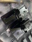
went to install the body lift, I bought a 2” puck kit from Mikellis, and thought I’d be content with that. Well then I saw that some manufacturers make a complete replacement frame mount style body lift and I liked that a lot more, well everything except the price tag. While on eBay I came across someone selling the frame style mounts and the price tag was still high but a bit more manageable so I bought them in 2”. Little did I know it would be of benefit to have the puck style kit because I would need parts off of it.

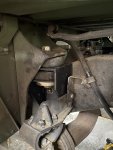
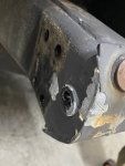
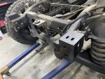
upon installing the rear brackets I noticed that they didn’t sit square to the frame. This is because there is a tube at the very end of the frame rail that prevents them from sitting flush. A quick google search and I found that they make spacers for this area. So I gotta wait till they show up to finish the rear brackets.

Not thrilled with the front frame lift brackets, they get rid of the hooks up front and I like having those, so I’ll remove them and use the pucks from the other lift.

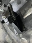
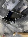
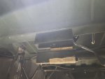
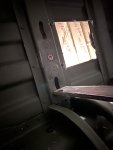
went to tackle the fuel tank spacers and the rear mount was easy, the crossmember has plenty of room to drill through. However not so with the forward mount, and no way to use a nut fastener on it, so I broke out some riv nuts.

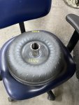
filling up the new torque converter with fluid.

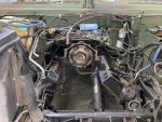
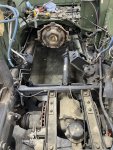
Once I get new longer bolts for the A pillar mounts I’ll install the engine. Much easier to mess with that while the engine is out.

motor mounts are here, and they are even labeled which side -how fancy.

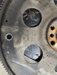
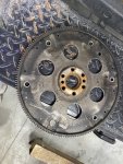
Also nice to see that the flex plate is labeled which side is which too, however it pretty much can only mount to the torque converter one way.
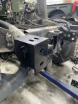
IMG_4800.jpegIMG_4801.jpegIMG_4876.jpegIMG_4878.jpegIMG_4880.jpegIMG_4881.jpegIMG_4882.jpegIMG_4883.jpegIMG_4885.jpegIMG_4886.jpegIMG_4888.jpegIMG_4889.jpegIMG_4891.jpegIMG_4890.jpegIMG_4892.jpegIMG_4893.jpeg
 
  • Like
Reactions: 98G

sail78385

Active member
97
110
28
Location
Charleston SC
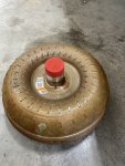
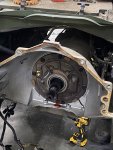
Ok so anyone following along -is there a proper distance I can measure to ensure the torque converter is seated all the way? I’m a Torqe converter rookie here. I was going to measure the factory converter but I believe it must have slipped forward some when I removed the engine. Of course I filled the new converter with a quart of ATF before hand. I will put a dab of grease on the center of it before mating it to the engine.

I had a really tough time finding out what the specs were of the Humvee’s torque converter. As much as I could find was that it’s a low stall. I bought a factory replacement for a 2500 truck with the 6.0 which is a 1800-2000 stall. I really have poor knowledge of torque converters, but i feel confident that what was behind the 6.5 diesel wouldn’t be appropriate for the 6.0 but I could be wrong.
IMG_4715.jpegIMG_4736.jpegIMG_4884.jpegIMG_4899.jpegIMG_4900.jpegIMG_4901.jpegIMG_4902.jpeg
 
Last edited:

sail78385

Active member
97
110
28
Location
Charleston SC
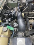
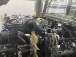
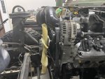
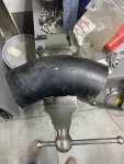
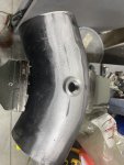
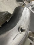
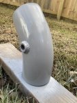
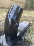
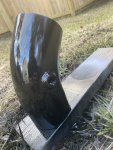
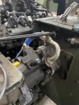
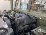
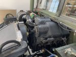
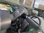
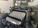
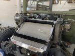
Came up with this for an air intake setup… also working on some other details right now that I hope work out well, but the parts have been delayed due to all the bad weather across the country. The Holley Terminator uses a MAT sensor so I had to put a npt bung on the tube. Came out ok for scrap metal. I should be able to move the fan a little more forward.

IMG_5192.jpegIMG_5194.jpegIMG_5195.jpegIMG_5293.jpegIMG_5294.jpegIMG_5295.jpegIMG_5296.jpegIMG_5297.jpegIMG_5298.jpegIMG_5299.jpeg
 

sail78385

Active member
97
110
28
Location
Charleston SC
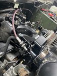
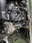
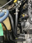
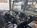
Working on some of the smaller things, knocked out the heater hoses and throttle cable today. I reused the throttle cable shield/hose from the Humvee but ran a new cable through it.
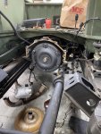
Looking at the Hydroboost setup I think the exposed fitting is pressure to pump and the one with the plug over it is return to pump?

I should have 1 non pressure line coming from the steering box that goes to the cooler and another from the pump going to the cooler?


IMG_5316.jpegIMG_5317.jpegIMG_5315.jpegIMG_5313.jpegIMG_5318.jpeg
 
Top
AdBlock Detected

We get it, advertisements are annoying!

Sure, ad-blocking software does a great job at blocking ads, but it also blocks useful features of our website like our supporting vendors. Their ads help keep Steel Soldiers going. Please consider disabling your ad blockers for the site. Thanks!

I've Disabled AdBlock
No Thanks