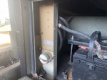
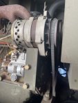
Its not a VR, its the A1, known as a "Thermal Watt Converter."
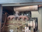
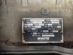
Have you downloaded the TM's? The MEP-004A and MEP-005A are same, same. Just a few more jugs on the 005.
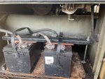
Get some batteries charged up and then we can do some troubleshooting. This is a wonderful gen set. I hate the ASK, but thats from working on too many of them in the dark!
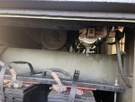
The Fault indicator panel is completely inop, so that will require some digging to diag and for whatever reason the stop-run-start switch becomes inop for a short time after a ride down the Road. Interesting bugs
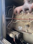
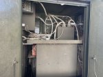
The A9, Fault Indicator is normally a fuse bad, OR, open it up and see if the relay is in it. The A9 was more or less a pluck and chuck item. But not hard to fix.
The S2, Run/Start/Stop switch problem sound like loose C-Plug on thew control panel or maybe a loose relay, (Same kind as in the A9) on the A4 Control Panel Relay Assy.
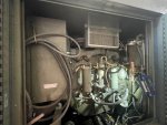
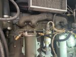
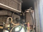
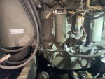
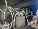
Please take a boat load of pictures, good ones. Maybe we can see things you do not know about.
Do not worry about the A1 for the time being. Set runs fine when the A9 has a melt down.


 To the TM’s!
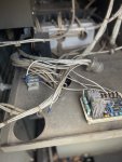
") if You need anything checked out.
if You need anything checked out.