- 14,734
- 5,221
- 113
- Location
- Buchanan, GA
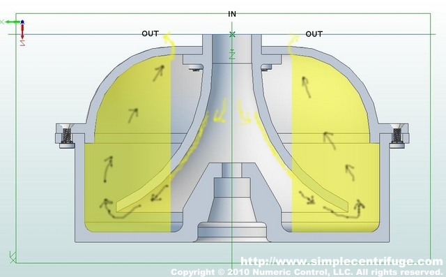
Honestly that's what you don't want. You basically want the oil to fall into the spinning canister. The centrifugal effect is how it filters. Think of it from a cross section view. Here's a pic that might help a little. Basically the oil drips into the spinning canister. The cross section of the canister is simply a ] shape. The rotation causes the oil to fill the cross section. The inertia carried by the heavier particles help settle them towards the outskirts of the canister. Allowing the lighter oil to move inwards. Eventually after so much oil is there, it starts flowing up towards the top where it finally is flung out. (Cleaned) If you were to introduce turbines like the converter originally had, you'd loose this ability for the fluid to freely "float" to the top.Just a thought, the turbine and impeller spinning at close to same speed give a high circular flow , just thinking it may tame the incoming fluid .
guessing about 10 pounds oil and the converter spinning , it's some good fab work and he is having fun it seems with tuning the process.
I like this because I get to learn something new from watching.
If the OP doesn't mind, I'll try to post up some pics of the setup I tinkered with. (I still have it actually) Same principal, much smaller scale.