• Steel Soldiers now has a few new forums, read more about it at: New Munitions Forums!

  • Microsoft MSN, Live, Hotmail, Outlook email users may not be receiving emails. We are working to resolve this issue. Please add support@steelsoldiers.com to your trusted contacts.

How to bypass PCB? I am aware some HMMWV owners have done it. TOBASH

sellers

New member
9
2
3
Location
Ohio
Hey Everyone!
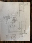
I'm a little new and haven't posted any thing before but wanted to run my idea by y'all. I've been following this thread and scheming to convert my SSI "smart" box to a bullet proof "dumb" box. Attached is my proposed schematic. The only thing I'm a little stuck on is what to do with pin G (Engine Connector). I know that it is the Alternator AC tap. Can I just leave it unconnected?

So this design will bypass the mess of MOSFETS, resistors, capacitors and diodes in the SSI remote control smart box. A momentary switch activates the glow plug relay and a wait light relay. The wait light relay is a SPDT and disconnects power to the lights when the switch is pushed. I added simple 1N4007 diodes as flyback diodes which should prevent any high voltage pulses when the relays are powered on/off. (I had a bunch sitting around do I didn't price them out). I'm planning on unsoldering my connectors and reusing my box and connectors. I'm guessing that this is close to what y'all did but if I got something wrong please let me know.
dumbbox.jpg
 

TOBASH

Father, Surgeon, Cantankerous Grouch
Steel Soldiers Supporter
Supporting Vendor
3,596
3,518
113
Location
Brooklyn, NY
I will post my diagrams later. I have a video to post BUT it is not edited.

Your diagrams Sellers are rudimentary. Not a bad start though.

I have the circuits totally mapped out BUT I have been busy managing patients and my practice to post or post the video. The Chinese Virus caused me to make my practice/patients a priority.
 

TOBASH

Father, Surgeon, Cantankerous Grouch
Steel Soldiers Supporter
Supporting Vendor
3,596
3,518
113
Location
Brooklyn, NY
Well. Here it is. I made one and it works... BUT:

This is a potentially dangerous high-voltage high amperage item and let me start by saying that I made this as an educational learning exercise and none of you should do it.

I am not an electrical engineer nor am I affiliated with any electrical company nor am I affiliated with AM General, and I take no responsibility should you be foolish enough to make one of these. This device is a fire hazard that causes a severe risk of death and damage and injury. You will make these things at your own risk. I repeat this was just an educational exercise. It is not meant to be installed in any vehicle.

This is posted for educational purposes only to better understand what a stupid waste of money a PCB and EESS really is.

These are the schematics. Video later today or this week.

First is general vehicle wiring, second is specific to PCB, third is legend and forth is parts list.

[EDIT = IMPORTANT! Diodes in schematic have been corrected 6/26/2022 EDIT.]
 

Attachments

Last edited:

TOBASH

Father, Surgeon, Cantankerous Grouch
Steel Soldiers Supporter
Supporting Vendor
3,596
3,518
113
Location
Brooklyn, NY
Hey, I confirmed these diagrams with you months ago Cam, so I blame you! LOL

[EDIT - And yes, you're correct.}

My unit works so the diodes are in properly.

I will correct later tonight, but I clearly wrote a disclaimer.
 
Last edited:

sellers

New member
9
2
3
Location
Ohio
Mr. T and CAMO,
Thanks a ton fellas! At my own risk I'm going to go ahead and build one of these (for educational purposes). I let the smoke out of my "smart" box and everyone knows that once the smoke is let out of electronics they don't work no more. I'll let y'all know how it goes.
 

leon 1970

New member
1
0
1
Location
florida
Can't wait to see U on the U tube. Have fire extinguisher off camera.

U kind of covered all the bases why not to build one.

My reality is if one can understands a couple of circuits (electricity 101 for dummies), is handy with a drill & motor, can work with a couple of 8-32 screws, can crimp & solder a few wires, buy a few parts for under 65 bucks... One will have conquered the not so magic, not so smart /ESSS boxes and never have to post "truck won't start, do I have a bad box" and shell out $500 bucks to find out.

NOW I am not saying if you got $500 buck to toss around to get rolling again (don't forget $100 more for glow plugs, if they go south) then that's a way to go. To add a OEM computer controller made some defense suppler's a boat load of return business. (google it) And still at a premium for hobby fun, OUCH!

As a hobby, I don't have a boat, just a simple HumV to toy with. Boss says no more $$$ for Mr. HumV. (got to be clever, had to get creative here)

So it was to the drawing board and came up with the plan. Under the hood of a HumV is about the simplest form of diesel engine. The electrics...ON or OFF. Just offering up another way to start the truck... OLD SCHOOL If it's a clicking, it's a working...LOL

Fail point are the same, could be a solenoid, could be a relay. Most of us have a handle on those items. Won't be a computer chip taking over my Mr. Humv.

Tobash, U missed the Oscars. Maybe I can wait, CAMO

CAMO and TOBASH have been working on this.. well he has for a couple of months. All for fun and fame, LOL
Do you have a schematic for this
 
Top
AdBlock Detected

We get it, advertisements are annoying!

Sure, ad-blocking software does a great job at blocking ads, but it also blocks useful features of our website like our supporting vendors. Their ads help keep Steel Soldiers going. Please consider disabling your ad blockers for the site. Thanks!

I've Disabled AdBlock
No Thanks