• Steel Soldiers now has a few new forums, read more about it at: New Munitions Forums!

  • Microsoft MSN, Live, Hotmail, Outlook email users may not be receiving emails. We are working to resolve this issue. Please add support@steelsoldiers.com to your trusted contacts.

How to bypass PCB? I am aware some HMMWV owners have done it. TOBASH

mmurphy001

New member
9
18
3
Location
Thor, Iowa
I tried this and it worked as designed but the wait to start light was unclear. The diagrams show both the “original” and a secondary WTS light/24v led connected. Without an “extra” WTS LED my box worked the glow plugs and everything else perfectly but the WTS light did not work. So I decided to explain a bit of what I did to get it working just in case anybody else hit this snag. I did skim all the comments but did not see anything about it.

To get the connection for the push button outside the PCB I reused the e-brake wire (67). (There's a letter behind it but I don't recall what it was).

I cut it out of the loom a few inches past the box. (the e-brake light still works) I hooked that and the (571) wire from my WTS light which happened to be LED. This took a bit since the WTS light won’t come out unless you pull the entire dash out a few inches. You connect the ground side of the secondary solenoid (or Glow Plug Relay in my mind) to Dash Body Harness Pin C find the 67 wire on the plug side and snip it and add a few inches of wire to it and connect it to a snipped 571 wire from the WTS light. The other side of the push button goes to ground.

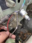
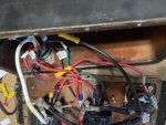
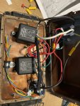
I’ve included a few pics, a couple of the inside of the box and the WTS light/push button.

A few notes:
  • My PCB box was riveted together, if yours is completely drill out all rivets before attempting to separate the halves the rivet stubs are a bear to get out.
  • I spent (wasted) a lot of time trying it to “save” as much as I could out of the old box. Don’t bother, gut it and start fresh.
  • Behind the dash on the firewall is a bar that comes close to the dash right where I wanted to install the button and probably would have drilled a hole first if I had not pulled the dash and found it interfered. I ended up horizontal with the start switch which worked out fine. You can see the hole next to the start switch in the picture. The WTS light is in my hand in the picture showing the two wire numbers.
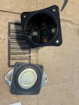
  • One last note, my PCB had three solenoids in it. Nothing was burned up but my WTS light just flashed briefly and the plugs never got hot. What I did find is one of the solenoids was a “dummy” one put there just for the terminals or it was defective because it was empty, no guts in it at all. I’m curious if anyone has found dummy solenoids in theirs or mine was just defective.

Finally, Thanks to everyone who contributed to this post. My HMMWV now starts on glow plugs and I believe with this mod it will work fine for a long time to come.
IMG-1425.JPGIMG-1424.JPGIMG-1427.JPGIMG-1426.JPG
 

TOBASH

Father, Surgeon, Cantankerous Grouch
Steel Soldiers Supporter
Supporting Vendor
3,569
3,475
113
Location
Brooklyn, NY
Happy you did this! Good on ya’!

The LED I included in the diagrams is to show if the glow plugs are functioning. If all 8 are dead, my LED won’t light BUT the dashboard “Wait Light”/LED will.

Happy to see the relays you used will support 200 amps each. Where did you source them and are the rated for continuous use? If they are not rated for continuous use they can blow in the open position and drain your battery and blow your glow plugs.
 
Last edited:

Milcommoguy

Well-known member
Supporting Vendor
1,708
2,261
113
Location
Rosamond, CA
I tried this and it worked as designed but the wait to start light was unclear. The diagrams show both the “original” and a secondary WTS light/24v led connected. Without an “extra” WTS LED my box worked the glow plugs and everything else perfectly but the WTS light did not work. So I decided to explain a bit of what I did to get it working just in case anybody else hit this snag. I did skim all the comments but did not see anything about it.

To get the connection for the push button outside the PCB I reused the e-brake wire (67). (There's a letter behind it but I don't recall what it was).

I cut it out of the loom a few inches past the box. (the e-brake light still works) I hooked that and the (571) wire from my WTS light which happened to be LED. This took a bit since the WTS light won’t come out unless you pull the entire dash out a few inches. You connect the ground side of the secondary solenoid (or Glow Plug Relay in my mind) to Dash Body Harness Pin C find the 67 wire on the plug side and snip it and add a few inches of wire to it and connect it to a snipped 571 wire from the WTS light. The other side of the push button goes to ground.

I’ve included a few pics, a couple of the inside of the box and the WTS light/push button.

A few notes:
  • My PCB box was riveted together, if yours is completely drill out all rivets before attempting to separate the halves the rivet stubs are a bear to get out.
  • I spent (wasted) a lot of time trying it to “save” as much as I could out of the old box. Don’t bother, gut it and start fresh.
  • Behind the dash on the firewall is a bar that comes close to the dash right where I wanted to install the button and probably would have drilled a hole first if I had not pulled the dash and found it interfered. I ended up horizontal with the start switch which worked out fine. You can see the hole next to the start switch in the picture. The WTS light is in my hand in the picture showing the two wire numbers.
  • One last note, my PCB had three solenoids in it. Nothing was burned up but my WTS light just flashed briefly and the plugs never got hot. What I did find is one of the solenoids was a “dummy” one put there just for the terminals or it was defective because it was empty, no guts in it at all. I’m curious if anyone has found dummy solenoids in theirs or mine was just defective.

Finally, Thanks to everyone who contributed to this post. My HMMWV now starts on glow plugs and I believe with this mod it will work fine for a long time to come.
View attachment 884083View attachment 884084View attachment 884086View attachment 884087
That's a Prestolite box. The dummy solenoid is not a solenoid. It is used has a high current binding posts.

Camo, As in Camoteksystems.com
 

cwc

Active member
Steel Soldiers Supporter
307
153
43
Location
Sweeden, KY
In post #3 (page 1 of this thread), point #1, I described a goal of keeping all of the modifications within the box, i.e. no modifications to the vehicle wiring harness, so that the box could be easily moved from one vehicle to another and provide identical function. In point #3, I described the function of the Wait light on the dash, i.e it is powered by wire 27, and illuminates when 571 is taken to ground inside the control box. (I guess I could have been more explicit - I mostly discussed what would happen if you tried to make the light come on by powering 571 out of the box, for example by connecting it to the output of the glowplug relay, no bueno.) In any event, the light could be made to illuminate in response to the glowplugs being energized. If you used a relay to provide this function it might look something like this:

Relay for wait light.JPG
 

TOBASH

Father, Surgeon, Cantankerous Grouch
Steel Soldiers Supporter
Supporting Vendor
3,569
3,475
113
Location
Brooklyn, NY
That's a Prestolite box. The dummy solenoid is not a solenoid. It is used has a high current binding posts.

Camo, As in Camoteksystems.com
Agreed about that being a Prestolite. I have several that I opened before creating this thread. Prestolite has robust solenoids that can be reused for a DIY project. Self tapping sheet steel screws will close it nicely. Drill the top hole larger than the bottom so the screws act like lag screws and pull the box closed and prevent water from leaking in. Alternatively, use sheet metal screws with nuts, or use rivets.

Genius as in “Genius Boxes”… “Because Smart Start systems ain’t that smart and don’t always start…”
 

TOBASH

Father, Surgeon, Cantankerous Grouch
Steel Soldiers Supporter
Supporting Vendor
3,569
3,475
113
Location
Brooklyn, NY
In post #3 (page 1 of this thread), point #1, I described a goal of keeping all of the modifications within the box, i.e. no modifications to the vehicle wiring harness, so that the box could be easily moved from one vehicle to another and provide identical function. In point #3, I described the function of the Wait light on the dash, i.e it is powered by wire 27, and illuminates when 571 is taken to ground inside the control box. (I guess I could have been more explicit - I mostly discussed what would happen if you tried to make the light come on by powering 571 out of the box, for example by connecting it to the output of the glowplug relay, no bueno.) In any event, the light could be made to illuminate in response to the glowplugs being energized. If you used a relay to provide this function it might look something like this:

View attachment 884104
My schematics show an external LED that you can mount anywhere. You can also disconnect the “wait light” from the dashboard system and connect to my box’ designed LED wires. Use Packard Connectors from my box to the stock “wait light” wires. Just make sure you get the polarity correct as LED’s are diodes and only accept current from one direction.
 

mmurphy001

New member
9
18
3
Location
Thor, Iowa
Thanks for the info on the dummy solenoid. I was indeed curious. I used pop rivets to put the box back together. Thanks for the clarification on the LED's. Since I only have one HMMWV I figured swapping booxes is not in the cards so I did not have any qualms about making a one-off. As for the solenoids I used, I don't remember where I got them (ebay or amazon) but they were advertised as continuous duty. The two (working) solenoids inside my box either were not marked or the part# could not be found online so I did not use them because I did not know if they were continuous duty or not. They seemed good, tested good but I did not trust them.
 

Ranchtruck

New member
19
12
3
Location
Texas
Well. Here it is. I made one and it works... BUT:

This is a potentially dangerous high-voltage high amperage item and let me start by saying that I made this as an educational learning exercise and none of you should do it.

I am not an electrical engineer nor am I affiliated with any electrical company nor am I affiliated with AM General, and I take no responsibility should you be foolish enough to make one of these. This device is a fire hazard that causes a severe risk of death and damage and injury. You will make these things at your own risk. I repeat this was just an educational exercise. It is not meant to be installed in any vehicle.

This is posted for educational purposes only to better understand what a stupid waste of money a PCB and EESS really is.

These are the schematics. Video later today or this week.

First is general vehicle wiring, second is specific to PCB, third is legend and forth is parts list.

[EDIT = IMPORTANT! Diodes in schematic have been corrected 6/26/2022 EDIT.]
Thank you for sharing all the info. I put one together yesterday and works as advertised. Saved me a lot of time and money, really appreciate it!
 

TOBASH

Father, Surgeon, Cantankerous Grouch
Steel Soldiers Supporter
Supporting Vendor
3,569
3,475
113
Location
Brooklyn, NY
Thank you for sharing all the info. I put one together yesterday and works as advertised. Saved me a lot of time and money, really appreciate it!

It literally warms my heart that you and others have used this posted thread to manufacture your very own bullet proof PCB.

You’re using the thread exactly as intended!
:giggle:

For all future visitors, post#51 has the clear schematics that will allow you to bypass the PCB/EESS forever.
 
Last edited:

gokeeper

New member
13
4
3
Location
Moville, iowa
Well. Here it is. I made one and it works... BUT:

This is a potentially dangerous high-voltage high amperage item and let me start by saying that I made this as an educational learning exercise and none of you should do it.

I am not an electrical engineer nor am I affiliated with any electrical company nor am I affiliated with AM General, and I take no responsibility should you be foolish enough to make one of these. This device is a fire hazard that causes a severe risk of death and damage and injury. You will make these things at your own risk. I repeat this was just an educational exercise. It is not meant to be installed in any vehicle.

This is posted for educational purposes only to better understand what a stupid waste of money a PCB and EESS really is.

These are the schematics. Video later today or this week.

First is general vehicle wiring, second is specific to PCB, third is legend and forth is parts list.

[EDIT = IMPORTANT! Diodes in schematic have been corrected 6/26/2022 EDIT.]
This is great work and so very helpful. Can you help me understand the wiring to Pin E on the dash side harness? It appears that is the output to the wait light but you have it connected to power? I understood that you needed to ground this pin to get the factory wait light to illuminate? I understand the idea behind the added led to actually signify the working glow plugs must also interested in what the modification does to the existing wait light I would have expected that pin wasn’t used and the light would not work?


Sent from my iPhone using Tapatalk
 

TOBASH

Father, Surgeon, Cantankerous Grouch
Steel Soldiers Supporter
Supporting Vendor
3,569
3,475
113
Location
Brooklyn, NY
Dash light becomes an indicator that you pressed the glow plug button and is no longer a wait light. My added LED will light when at least one glow plug is active. I no longer build or sell the units with that added LED.
 

cwc

Active member
Steel Soldiers Supporter
307
153
43
Location
Sweeden, KY
Can you help me understand the wiring to Pin E on the dash side harness?


Sent from my iPhone using Tapatalk
The Wait-to-Start lamp is powered from the Master Start Switch when in the Run position. The lamp illuminates when the circuit is completed when 571 (terminal E) is taken to ground inside the Protective Control Box, as shown on the attached snips from the larger diagram found near the end of TM9-2320-280-20-3 Part 3. In posts #3 and 64, I mentioned my preference to have all of the functionality built into the box so that it is not necessary to make any wiring connections (other than connecting the wiring harness connectors) or mount any lights or pushbuttons. So I mount a momentary toggle switch or pushbutton on the box for activating the glowplugs, and add a small 24 VDC relay to drive the Wait-to-Start light as an indicator of glowplug activation. To conect the relay, drive the coil of the relay off of the output of the glowplug relay, and then take wire 571/terminal E to ground through a set of contacts.

Note that if you connect wire 571/terminnal E to the output of the glowplug relay, then the action will be backwards. When the glowplugs are energized, the lamp is powered from both sides and will not light. Then when the glowplugs are off, the lamp finds ground through the glowplugs, and the glowplugs will actually be powered slightly, by whatever current the lamp passes.

Wait to start lamp power supply.jpg

Wait to start lamp.jpg

24 VDC relay with socket.jpg
 

Humpty

Member
68
57
18
Location
South Dakota, USA
If anybody needs values off a KDS board for repairs lemme know. This intact board had a burned trace on the bottom that was keeping the solenoid engaged and killing my battery. (and eventually roaching the solenoid contacts)

Converted the box to manual glow op and the info in this thread was very helpful.
 

Attachments

Top