• Steel Soldiers now has a few new forums, read more about it at: New Munitions Forums!

  • Microsoft MSN, Live, Hotmail, Outlook email users may not be receiving emails. We are working to resolve this issue. Please add support@steelsoldiers.com to your trusted contacts.

I got the new gauges in

95blklsc

Member
39
0
6
Location
MA
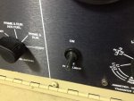
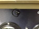
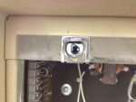
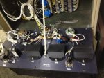
I bought the gauge kit from Jim after my frequency transducer went out. They look pretty good too! I love the extra information it gives me about load balancing. It was a good excuse to also put in the new panel I've had sitting on the shelf for a few months. I also did a few upgrades that I noticed in Jim's pictures, I put a waterproof switch boot on as well as 1/4 turn DZUS fasteners on the panel. I still plan on putting some SS fasteners on the DC breaker and painting it as well to match the rest of the panel.


Switch boot (quantity is 15): http://www.amazon.com/gp/product/B008DS0NWQ/ref=oh_details_o00_s00_i00?ie=UTF8&psc=1
1/4 DZUS Fastener: http://www.kurveygirl.com/shop/product_info.php?products_id=190

I could have gone up one size in diameter on the DZUS fasteners without a problem. I also could have gone 1-2mm more in length so I wouldn't have had to squeeze the retaining clip a bit, but all in all it fits just fine with a little adjustment.

(pictures of my whole project if you are interested https://plus.google.com/photos/1050...ms/5922725248166718785?authkey=CLKfr9PEpILxDA)
7.jpgphoto_1(1).jpgphoto_2(1).jpgphoto_3.jpg9.jpg8.jpg6.jpg
 
Last edited:

95blklsc

Member
39
0
6
Location
MA
The frequency gauge is basically plug and play. The dual voltage/current gauge is slightly more complicated but not hard. You need to take off four bolts to remove the top of the output box and remove the cables going to L1 and L3 to put the current transducer coils on then hook the output cables back up. The you need to drill a hole to get the transducer wires out of output box. You run these up through the drain hole into the control box then hook them up to the gauges. If you want to monitor each leg to neutral you need to bring a neutral feed up otherwise you can only read 240 on each gauge.
 

m16ty

Moderator
Moderator
Steel Soldiers Supporter
9,580
218
63
Location
Dickson,TN
I got my Jim frequency gauge installed and it works great.

I need to also pick up a couple of current/volt gauges but I'm not going to install them in the generator. I'm going to put them in a box right beside the house breaker box. I figure I can balance loads easier when I can watch the gauges as I flip the breakers and not have to go outside and check the generator.
 

Ray70

Well-known member
Steel Soldiers Supporter
2,679
6,267
113
Location
West greenwich/RI
M16ty, that's an excellent idea, putting gages at the breaker panel.
Looks like I'll be contacting Jim shortly myself, started up one of my -002a's the other night now and the HZ gage pegs itself high, so I've most likely lost yet another frequency transducer. Just need to decide if I should replace the one gage or bite the bullet and go with the gage trio!
 

cuad4u

Active member
268
89
28
Location
St Matthews, SC
M16ty, that's an excellent idea, putting gages at the breaker panel.
Looks like I'll be contacting Jim shortly myself, started up one of my -002a's the other night now and the HZ gage pegs itself high, so I've most likely lost yet another frequency transducer. Just need to decide if I should replace the one gage or bite the bullet and go with the gage trio!
The Hz gauge on my 002A was reading about 5 Hz high. When my Fluke 87 VOM indicated 60 Hz the gauge on my 002A showed 65 Hz. Having nothing to lose I experimented by adding a a few different resistors in series with the built in Hz gauge until it read 60 Hz while the Fluke 87 was also reading 60 Hz. Finding the correct value of resistor was by trial and error. In my case the resistor needed was 560 ohms. Now when my Fluke 87 VOM reads 60 Hz, the gauge in the 002A also reads 60 Hz.

The purpose of the transducer is to input AC from the generator and convert it to DC. The DC output from the transducer increases and decreases "in step" with the AC Hz from the generator. The DC output from the transducer then "drives" the Hz gauge which is nothing more than a DC milli-amp meter. Adding a resistor will only "work" if the built in Hz gauge reads high. I do not know of any "fix" if the gauge is reading low. Your results may vary.
 
Last edited:

Ray70

Well-known member
Steel Soldiers Supporter
2,679
6,267
113
Location
West greenwich/RI
If you have a HZ gage that is working but rerading a little off there are 2 adjustments you might be able to make to correct it.
The gage has a screw at the bottom of the needle ( at least the full glass ruggedized ones do ) that I think will allow you to make slight adjustments to the needle's position.
Also on the back of the transducer, some of them are potted in a soft brown silicone foam material. The circuit board is mounted vertically in the center, perpendicular to the screw terminals. You may see 2 potentiometers just at the surface, or you may need to scrape out a tiny bit of the silicone to find the screws. These screws can be used to adjust the gage reading, but I do not know the correct procedure to do so. All I can tell you is that turning the screws will move the gage needle. If yours is potted in the hard black epoxy you might be out of luck finding the screws.
Unfortunately I think mine is beyond adjustment.... I think the transducer went out to lunch, but I still have to remove it and I'll throw a suicide cord on it and a spare gage and see what happens. If its bad I'll just go with Jim's gage rather then paying for another transducer, that will probably die at the most inoppourtune moment....
 

TurboJoe

New member
68
2
0
Location
Lafayette, NJ
If you have a HZ gage that is working but rerading a little off there are 2 adjustments you might be able to make to correct it.
The gage has a screw at the bottom of the needle ( at least the full glass ruggedized ones do ) that I think will allow you to make slight adjustments to the needle's position.
Also on the back of the transducer, some of them are potted in a soft brown silicone foam material. The circuit board is mounted vertically in the center, perpendicular to the screw terminals. You may see 2 potentiometers just at the surface, or you may need to scrape out a tiny bit of the silicone to find the screws. These screws can be used to adjust the gage reading, but I do not know the correct procedure to do so. All I can tell you is that turning the screws will move the gage needle. If yours is potted in the hard black epoxy you might be out of luck finding the screws.
Unfortunately I think mine is beyond adjustment.... I think the transducer went out to lunch, but I still have to remove it and I'll throw a suicide cord on it and a spare gage and see what happens. If its bad I'll just go with Jim's gage rather then paying for another transducer, that will probably die at the most inoppourtune moment....
I am not familiar with the Mep-02, but I have been in the metering business my whole life. While I no longer calibrate meters, I have built, modified, and calibrated thousands and thousands of meters. I have a bit of a good background here.

It seems they use a frequency transducer that outputs a proportional output to the meter. The meter being a DC meter only has one adjustment that you can do at home. The front cover screw is the zero adjuster. When power is off to the meter this adjuster changes mechanically where the span starts and stops, IE. set the span to start at the far left or 55.

Adding a resistor in series with the meter works, however it may be not accurate. The frequency transducer, if like any other has two trim pots. One pot sets the zero, the other sets the span. It gets a tad more complex because zero isn't actually zero it is 55 hz. To calibrate the transducer you would need a way to create 55 hz, either slowing the generator down to 55 or with a function generator. Then set the zero pot so everything reads 55. After that you would need to run up to 65 hz, and use the span pot to run it to 65. Some playing should give you a good idea which pot does what, the span will have much greater influence on the meter. After you have zero, and the full span lined up correctly, 60 should be right on.

For what its worth, to calibrate a 1mA DC movement that is reading low we use a magnet charging coil and machine to add to the magnetism. This is generally a very course adjustment so after that it needs to be brought back down into spec with a demagnetizing coil. Back when I did that every day I could fully calibrate a meter to with in 2% accuracy in under a minute :).

We do sell frequency transducers, and meters. We don't generally sell the round style, but I can get you in touch with a shop that does. If the meter isn't sealed then I can most likely calibrate it also. PM me if your interested.
 

cuad4u

Active member
268
89
28
Location
St Matthews, SC
I am not familiar with the Mep-02, but I have been in the metering business my whole life. While I no longer calibrate meters, I have built, modified, and calibrated thousands and thousands of meters. I have a bit of a good background here.

It seems they use a frequency transducer that outputs a proportional output to the meter. The meter being a DC meter only has one adjustment that you can do at home. The front cover screw is the zero adjuster. When power is off to the meter this adjuster changes mechanically where the span starts and stops, IE. set the span to start at the far left or 55.

Adding a resistor in series with the meter works, however it may be not accurate. The frequency transducer, if like any other has two trim pots. One pot sets the zero, the other sets the span. It gets a tad more complex because zero isn't actually zero it is 55 hz. To calibrate the transducer you would need a way to create 55 hz, either slowing the generator down to 55 or with a function generator. Then set the zero pot so everything reads 55. After that you would need to run up to 65 hz, and use the span pot to run it to 65. Some playing should give you a good idea which pot does what, the span will have much greater influence on the meter. After you have zero, and the full span lined up correctly, 60 should be right on.

For what its worth, to calibrate a 1mA DC movement that is reading low we use a magnet charging coil and machine to add to the magnetism. This is generally a very course adjustment so after that it needs to be brought back down into spec with a demagnetizing coil. Back when I did that every day I could fully calibrate a meter to with in 2% accuracy in under a minute :).

We do sell frequency transducers, and meters. We don't generally sell the round style, but I can get you in touch with a shop that does. If the meter isn't sealed then I can most likely calibrate it also. PM me if your interested.
Joe - You are 100% correct. I never meant to infer that by adding a resistor in series with the Hz gauge in my 002A that it still held perfect calibration all the way across the meter face from 55 - 65 Hz. However IN MY CASE adding the resistor definitely made the Hz gauge on the 002A metering panel agree with my Fluke 87 VOM at 60 Hz and just above and just below 60 Hz. After all that is where we really want the 002A gauge to be most accurate. Since I do a lot of radio repair and restoration, I have a rather extensive electronics shop, including several function generators that are quite accurate. Time permitting I may "sweep" the transducer in the 002A to see if the built in Hz gauge is still accurate all the way across the dial after installing the resistor. Regardless shortly I will replace the gauge in question with one of the digital meters referenced above. I think that is the way to go if the built-in Hz gauge is screwy.
 

95blklsc

Member
39
0
6
Location
MA
Great info about the old frequency transducer. I would love to know what component fails in these, mine is not very old. It went through a tier two reset in 07 and it only has about 25 hours on it at this point. It appears that everything in the control box was replaced, so I'm confident this isn't an old part on my unit. Failure after such a short period is very surprising and unacceptable.

The only potential issue (I don't think it is a big one) is the new digital frequency gauge seems to read 0.5 Hz low on mine. If there is an adjustment on it, you can't get to it with the 3D printed housing on. I figure that I know it reads a little low so I just set it accordingly.
 

TurboJoe

New member
68
2
0
Location
Lafayette, NJ
Joe - You are 100% correct. I never meant to infer that by adding a resistor in series with the Hz gauge in my 002A that it still held perfect calibration all the way across the meter face from 55 - 65 Hz. However IN MY CASE adding the resistor definitely made the Hz gauge on the 002A metering panel agree with my Fluke 87 VOM at 60 Hz and just above and just below 60 Hz. After all that is where we really want the 002A gauge to be most accurate. Since I do a lot of radio repair and restoration, I have a rather extensive electronics shop, including several function generators that are quite accurate. Time permitting I may "sweep" the transducer in the 002A to see if the built in Hz gauge is still accurate all the way across the dial after installing the resistor. Regardless shortly I will replace the gauge in question with one of the digital meters referenced above. I think that is the way to go if the built-in Hz gauge is screwy.
Honestly how you fixed it is exactly how I would do it also for that situation. Unless the mep-002 has a frequency adjuster that you can easily use the generator to move up and down to set the range of the transducer.

Those digital gauges do look nice.
 
Top
AdBlock Detected

We get it, advertisements are annoying!

Sure, ad-blocking software does a great job at blocking ads, but it also blocks useful features of our website like our supporting vendors. Their ads help keep Steel Soldiers going. Please consider disabling your ad blockers for the site. Thanks!

I've Disabled AdBlock
No Thanks