• Steel Soldiers now has a few new forums, read more about it at: New Munitions Forums!

  • Microsoft MSN, Live, Hotmail, Outlook email users may not be receiving emails. We are working to resolve this issue. Please add support@steelsoldiers.com to your trusted contacts.

Kinda got carried away..... M1028 rebuild

Sharecropper

Well-known member
Steel Soldiers Supporter
1,836
989
113
Location
Paris KY

dougco1

Well-known member
Steel Soldiers Supporter
869
649
93
Location
Cooperstown NY
Sharecropper,

Have you considered insulating the engine compartment / cabin?

Some good ideas from article titled;

"Sound and Heat Insulating a Diesel Hummer"

see URL https://www.flashoffroad.com/Improvements/Insulate_diesel/kopelson/Insulate.htm

If interested also look up information on "Lizard Skin" both heat and sound products; https://www.lizardskin.com

Regards

Joseph
I think that chevy civi diesel trucks/Suburbans had factory heat and sound insulation on the firewalls. Not sure if its still available or not. Just thinking.
 

Sharecropper

Well-known member
Steel Soldiers Supporter
1,836
989
113
Location
Paris KY
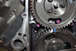
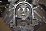
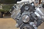
Here's an update. Taking my time and enjoying it immensely.

Installed a new IP driven gear. I could have purchased a used gear off Ebay, but because the P400 drive gear is new, I wanted to use a new driven gear so that the wear patterns on both gears would mature together. I sourced new M8-1.25 x 25mm flange bolts from McMaster and torqued all three to 30 foot-pounds, which is 10 pounds more than the TM specifies. Used blue Loctite on the threads and red Permatex 81950 Ultra-Slick Engine Assembly Lube on the gear teeth. Turned the engine over a few times with a pull handle and 24mm socket on the harmonic balancer to spread the pre-lube evenly on all teeth. It's surprising how easy the engine turns by hand. Probably the easist I have ever experienced. To index the timing of the driven gear correctly, the engine must be turned until the timing dot on the drive gear is at 12:00, then the driven gear should be meshed onto the drive gear at 6:00 with the two dots aligned. Failure to do this will result in the engine refusing to crank, period.

Next I will mount the new FlowKooler hi-volume water pump and oil filler tube. Here are a couple photos of my progress so far -
 

Attachments

ken

Active member
Steel Soldiers Supporter
2,479
25
38
Location
Houston Texas
Mike ,
Give me a call. I have more, I will ship out some more in the morning . I would like to get those pics to file a claim. I insured them.
 

Sharecropper

Well-known member
Steel Soldiers Supporter
1,836
989
113
Location
Paris KY
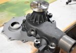
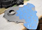
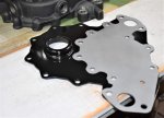
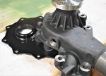
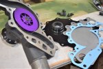
OK here is an update - I received the FlowKooler high-volume clockwise-rotation water pump and Fel-Pro gaskets. Before assembling, however, I media-blasted the water pump backing plate and treated it with Etch-Prep. I then laid the backing plate down with the FlowKooler in position, and penciled the outline of the water pump onto the backing plate. I then taped off the area which will be behind the water pump, and painted the backing plate with Rustoleum High Temperature Engine black paint. I did not want to paint the area behind the water pump because I wanted my gaskets and gasket sealer to adhere directly metal-to-metal. After the paint had dried I removed the tape and assembled the FlowKooler to the backing plate with the M8 bolts from behind. I then applied gasket sealer and the larger Fel-Pro gasket to the perimeter of the backing plate and installed the entire assembly to the engine. All M8 bolts were torqued to 20 foot pounds and the M10 studs were torqued to 35 foot pounds per the TM. Here are a few photos -
 

Attachments

richingalveston

Well-known member
1,715
120
63
Location
galveston/Texas
If you have time to elaborate on the oil filter mod you are installing then please share. I have the valve cover with oil cap opening and I will have the motor out so it may be something I should consider.
if it is in this post somewhere then please point it out. I have been through it (been here since the beginning).


Thanks
Rich
 

Sharecropper

Well-known member
Steel Soldiers Supporter
1,836
989
113
Location
Paris KY
Rich - I fully intend to photo-document everything I do to my P400, including the Spinner centrifugal filter install. Regarding that, I am now in the process of engineering and fabricating a mock-up model bracket for the Spinner to mount on. The Spinner CF spins the oil at 6000 RPM via normal oil pressure, and this centrifugal force sends all contaminants in the oil outwards to accumulate on the outer wall of the spinning vessel. The oil circulating in the center of the vessel is clean and without contaminants, and then drains back into the engine through the PCV opening in the valve cover. Regular round paper oil filters used on automobile engines today will filter contaminants in size down to around 20 micron, however as these filters accumulate the contaminants 20 micron and larger, they become even less effective. The Spinner centrifugal filter will remove contaminants in size down to less than 1 micron, which is the size of a germ's body. The "black" in used motor oil is contaminants, mainly microscopic carbon particles from piston ring blow-by. The Spinner centrifugal filter will remove these carbon contaminants non-stop during every minute that the engine is running.

When my P400 arrived, the valve cover with the PCV opening was on the passenger side, however there was no way to make the spinner work on that side with the air cleaner intake and 6.2 PCV valve in the way. Over on the driver's side, however, there was plenty of room, so I swapped valve covers so that the P400 PCV opening would be on the driver's side. In engineering the bracket for the spinner to mount on, I am designing a 1/4" steel plate with an attachment point from at least one intake bolt and down to 2 valve cover bolts. I will post photos of this bracket when I get it finished. To power the Spinner, I plan to feed it via a AN hose and fitting from the front of the passenger head port, where a turbo would normally get it's oil supply. Because I do not plan to turbo, this port will be ideal because it is downstream from the cam bearings in the oil galley. If I were planning to turbo, I would probably obtain the Spinner oil feed from the large oil port above the paper filter on the driver's side.

Stay tuned, it's beginning to get fun.
 

Jozseph

Member
216
0
16
Location
New York
Sharecropper,

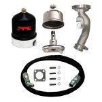
Did you review / look at one way the Spinner filter are mounted on a Duranax?

See photo, the casting on upper right
114010400_PPE.jpg

I would consider making an aluminum casting of the oil filling tube with an mounting platform for the spinner.

Regards

Joseph
 

Sharecropper

Well-known member
Steel Soldiers Supporter
1,836
989
113
Location
Paris KY
Sharecropper,

Did you review / look at one way the Spinner filter are mounted on a Duranax?

See photo, the casting on upper right
View attachment 744628

I would consider making an aluminum casting of the oil filling tube with an mounting platform for the spinner.

Regards

Joseph
Yes I studied that kit in depth before embarking on my effort to fabricate a custom bracket. The casting in that kit is unique to the Duramax and will not work on the front of a 6.2/6.5. I wish that it would, because it would certainly make it easier to add the Spinner to my system. I’m almost finished with the engineering for a custom bracket for any 6.2/6.5 and when I get finished I will post the plans on SS for anyone who wants them.
 

Sharecropper

Well-known member
Steel Soldiers Supporter
1,836
989
113
Location
Paris KY
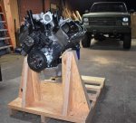
While waiting on my metal fabricator to produce the Spinner bracket, I became uncomfortable with the ability of my engine stand to hold the weight of the P400 as I continued to add parts. So I jumped into my shop and designed/built a laminated beam cradle for the engine to sit in during dress-up. By getting the engine off the stand and into the cradle, I can now go ahead and mount the 700R4 transmission.
 

Attachments

Sharecropper

Well-known member
Steel Soldiers Supporter
1,836
989
113
Location
Paris KY
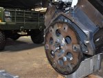
Update - got my NOS flex plate cleaned and installed. GM part number 14077158. Found it on Ebay for $50 with free shipping. Would rather have this original US-made part than the cheap Chinese stuff available. It had slight surface rust on the gears but quick work with a fine wire wheel brought it back to as-new condition. A light coat of WD40 will keep it rust-free until everything is finished.

I was a little surprised that the flex plate bolt holes on the rear of the crank were not metric, as everything else on the engine is metric. But the threads are SAE 7/16"-20 fine thread. I looked on Summit and there were several suppliers of these bolts, but all bolts offered were only 5/8" long. I measured the depth of the threaded holes on the end of the crank and all were 1-1/8" deep, so I ordered 1" long Grade 8 flange bolts from McMaster, part #92316A341. Used blue Loctitie and torqued all 6 bolts to 65 foot pounds per TM. Now I am looking for a new HMMWV 24-volt starter.
 

Attachments

ken

Active member
Steel Soldiers Supporter
2,479
25
38
Location
Houston Texas
Measure the thickness of you bolt head. I know flange bolts can be pretty thick. The OEM bolts are very thin. This is so they can clear the torque converter. If the ones you have are too tall, the converter will hit them before the hub enters the crankshaft bore. This would also keep the bell housing from mating all the way too the block.
 

Sharecropper

Well-known member
Steel Soldiers Supporter
1,836
989
113
Location
Paris KY
Measure the thickness of you bolt head. I know flange bolts can be pretty thick. The OEM bolts are very thin. This is so they can clear the torque converter. If the ones you have are too tall, the converter will hit them before the hub enters the crankshaft bore. This would also keep the bell housing from mating all the way too the block.
Ken - thanks for the heads-up. I will measure them tomorrow and report back.
 

ken

Active member
Steel Soldiers Supporter
2,479
25
38
Location
Houston Texas
Mike,
I just went out to the garage and measured one. It is .215 thick. So 1/32 less than a 1/4 inch.
 

Sharecropper

Well-known member
Steel Soldiers Supporter
1,836
989
113
Location
Paris KY
Measure the thickness of you bolt head. I know flange bolts can be pretty thick. The OEM bolts are very thin. This is so they can clear the torque converter. If the ones you have are too tall, the converter will hit them before the hub enters the crankshaft bore. This would also keep the bell housing from mating all the way too the block.
Ken - GOOD CATCH! You are correct, the flange bolt heads are too high to clear the torque converter. Whew, that was close! I owe you a cowboy steak!

I'm ordering the correct flex plate bolts now from Summit.
 

ken

Active member
Steel Soldiers Supporter
2,479
25
38
Location
Houston Texas
Ken - GOOD CATCH! You are correct, the flange bolt heads are too high to clear the torque converter. Whew, that was close! I owe you a cowboy steak!

I'm ordering the correct flex plate bolts now from Summit.
Glad I could help. That's what SS is all about.
 
Top
AdBlock Detected

We get it, advertisements are annoying!

Sure, ad-blocking software does a great job at blocking ads, but it also blocks useful features of our website like our supporting vendors. Their ads help keep Steel Soldiers going. Please consider disabling your ad blockers for the site. Thanks!

I've Disabled AdBlock
No Thanks