Z.T.R. ZERO TURNING RADIUS for trailer !
-
Steel Soldiers now has a few new forums, read more about it at: New Munitions Forums!
LMTV Hitch Extension Kit installed!
- Thread starter Awesomeness
- Start date

More options
Who Replied?Whoa, what the hell do you mean…I never had it!Man your loosing it!!!

- 1,814
- 1,523
- 113
- Location
- Orlando, FL
Yes, that's the step bumper. I have one too, and if you get the actual new kit, it comes with a new rear tailgate kit that is split in the middle, and opens like double doors / barn doors, instead of the single drop-down tailgate. I haven't installed the tailgate, but I have it.
A couple of questions if you don’t mind.We've been taking advantage of the coronapocalypse to get some work done, and we finally got the hitch extension kit installed.
Next project is the winch!
- I have the rear step bumper, and with the bumper on the trailer neck hits the bumper, so I'm hoping this gives it enough clearance. Is that what this extension is actually for, or is it for something else?
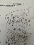
- Everything is covered in TM 9-2320-365-34-2, 18-2. M1078/M1079 PINTLE HOOK EXTENSION KIT INITIAL INSTALLATION
- Under INITIAL SETUP - Equipment Conditions, it says "Cargo bed removed, if equipped (para 15-
.". Yeah, we did not remove the bed! Some parts are a bit of a hassle, but it's still totally doable. Taking the bed off would be a huge pain, so I don't understand why they would even suggest that. At the end, you have 16 bolts left over, that I assume were to reinstall the bed, but interestingly they are NOT huckbolts (thank god).
- It has a lot of bracing and stuff, a ridiculous amount actually (150lb worth). The pintle goes from being installed through a 1/2" steel plate on the truck, to inside a 1/2" plate box, plus a new frame cross-member and bracing. I wonder if the kit is a "one size fits all", including MTVs and trucks with heavier towing capacities? We installed it all anyway.
- The instructions have you remove 4 huckbolts. An easy way to do this is to use a cutoff wheel into the side of the huckbolt, just where the smooth collar meets the hex head. In this area of the fastener there are no threads, so once you cut through the bolt inside it just falls off (some needed a whack from a hammer).
View attachment 793668- You need to drill 4x 3/4" (or 19mm) holes in the back plate cross-member of the truck. We rented a mag drill, and used a 3/4" hole saw. The mag drill took a little careful positioning to be able to reach all the holes, but worked. The 3/4" hole saw wobbled some and actually cut holes about 13/16" (~0.050" oversized), mostly because the rental drill has been abused, but the holes worked fine. This metal drilled fine, and did not appear to be hardened... the bit is still nice and sharp.
View attachment 793669
View attachment 793670- After that it was mostly bolt together. Putting the L-brackets that hold the wiring in place back on was a bit of a hassle, because it's hard to reach up in there. (Still not worth taking the bed off! Are they nuts?) Looks good complete, though I'll have to get the CARC out and paint it. I haven't been able to test it with the trailer yet.
View attachment 793671
View attachment 793672
1) How long did the entire job take?
2) Was / were there any tools, materials, or supplies you should have on hand that you hadn’t thought about?
3) The TM doesn’t say to remove the shock completely; it just says to “move (rotate top) away & out of the way”. Did you need to loosen the lower shock mount?
4) The rear crossmember support spacers - were they a ‘hammer fit’ or slid right in?
5) Do you recommend installing the rear cross member lower support prior installing the new rear cross member support between the frame rails? Install it as 1 unit basically?
6) What would you have done differently?
- 1,814
- 1,523
- 113
- Location
- Orlando, FL
It's been 2.5 years now since we installed it. I'll try to answer your questions, but some of it I don't remember. That in itself is a good thing, because that means it went together fairly straightforwardly, and there are no memorable events (e.g. "spent 10 hours trying to pound a part into place" didn't happen).A couple of questions if you don’t mind.
1) How long did the entire job take?
2) Was / were there any tools, materials, or supplies you should have on hand that you hadn’t thought about?
3) The TM doesn’t say to remove the shock completely; it just says to “move (rotate top) away & out of the way”. Did you need to loosen the lower shock mount?
4) The rear crossmember support spacers - were they a ‘hammer fit’ or slid right in?
5) Do you recommend installing the rear cross member lower support prior installing the new rear cross member support between the frame rails? Install it as 1 unit basically?
6) What would you have done differently?
1.) 24.5 hours, across 7 days (I keep track in a spreadsheet)
2.) Aside from renting the magnetic drill press, I don't recall needing anything else. However, I do already own a LOT of tools, as in "one of every hand tool Craftsman sells".
3.) I don't think we took off or loosened the shock mount at all.
4.) I don't remember hammering anything in that was hard to get to fit... it all went together pretty easily. It did take a bit of work to fish the parts up in place without taking the whole bed off the truck, but it's totally doable.
5.) I don't remember.
6.) I don't remember, however, I wrote the original post for a reason, and if there had been important information like that I would have shared it then. So I assume there aren't any significant things that stood out to me then.
Thank you. I am not anticipating getting it done in one day. Like you, I own more tools than a man should ever need. I am not inclined to rent a mag base drill. I’ll more than likely incrementally drill bigger holes until I get to 3/4” - 19mm.It's been 2.5 years now since we installed it. I'll try to answer your questions, but some of it I don't remember. That in itself is a good thing, because that means it went together fairly straightforwardly, and there are no memorable events (e.g. "spent 10 hours trying to pound a part into place" didn't happen).
1.) 24.5 hours, across 7 days (I keep track in a spreadsheet)
2.) Aside from renting the magnetic drill press, I don't recall needing anything else. However, I do already own a LOT of tools, as in "one of every hand tool Craftsman sells".
3.) I don't think we took off or loosened the shock mount at all.
4.) I don't remember hammering anything in that was hard to get to fit... it all went together pretty easily. It did take a bit of work to fish the parts up in place without taking the whole bed off the truck, but it's totally doable.
5.) I don't remember.
6.) I don't remember, however, I wrote the original post for a reason, and if there had been important information like that I would have shared it then. So I assume there aren't any significant things that stood out to me then.
- 8,237
- 20,802
- 113
- Location
- Charlotte NC
.Thank you. I am not anticipating getting it done in one day. Like you, I own more tools than a man should ever need. I am not inclined to rent a mag base drill. I’ll more than likely incrementally drill bigger holes until I get to 3/4” - 19mm.
If you ever get your hands on a Magnetic Base drill - you won't ever drill anything "frame related" without one. Yeah, the Milwaukee compact version is a thousand bucks and that is a lot of money but your time has to be worth something.
Long ago, I built a version that was just a half inch drill attached to a stand rotated ninety degrees. Had a small chain and hook arrangement to keep the drill from backing away from the frame. Example is in the picture below...

I purchased the pintle hook extension kit from Wheelspinner.
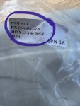
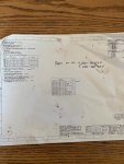
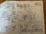
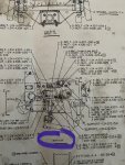
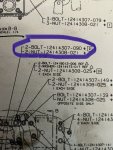
In the wooden crate there were engineer prints. They were in very rough shape so I photocopied them. The diagrams were small sized but the pictures helped (I could have enlarged them on my copier but didn’t need to). The biggest benefit of those prints is that it stated exactly which nuts & bolts (by part #) went where.
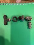
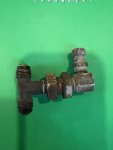
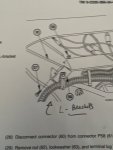
The pintle hook extension kit is 98% in. All that’s needed is to fab a relocation bracket for the 2 rear axle vent tube bulkhead T fitting.
The supplied upper support cross member will not go in unless you remove that bulkhead (pass through) fitting.
I did not remove the bed as the TM called for. And as also stated by other members there are some real tight spots that even with the bed removed would not have made access easier. The tightest place to access is the 5 (not 6 as the TM. Calls out) bolts & nuts that secure the air valve support brackets to the frame rails and the hardware for the two L brackets.
I didn’t want to remove the two 22 year old air lines so I tried to get the air valve support cross member pulled back enough to slide that new upper pintle support in - no dice. So off came the lines.
CAUTION: I’ve had lots of experience with these types of brass fittings and with such space restrictions it’s easy to cross thread those. Be patient and thread on with your fingers until you cannot turn anymore. Visually check before tossing a wrench on them. Ideally, the ferrule (wedding bands) should be replaced. I’ve reused them before with a great deal of success so I held my breath and put ‘em right back on.
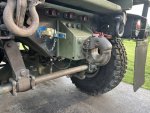
I have a Ingersol Rand 1” electric impact. It wouldn’t budge some of those upper shock mount bolts. Out came the flame wrench. A word of caution here: there are air lines and electrical harnesses on the inside of the frame rails in the proximity of where these bolts are. The frame and brackets those bolts are secured to act as heat sinks. I used my garden hose to keep the inside of the frame rail and hoses & harnesses cool while cutting. I was not about to take a chance and ruin a harness or burn up an air line.
I did not pull the top bolt & lower the sway bar down. Had I done so it would have helped give better access but it really didn’t hold up progress.
I used a hand drill to drill out the four holes for the extension bracket. I drilled the pilot holes and worked my way up in drill sizes until I got to 3/4”. I drizzled some cutting oil on the bit as I went. Smooth sailing!
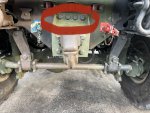
To get the huge nut off the back of the pintle I latched a pipe wrench on it with a cheater bar and used a tankers bar (wrecking bar) to turn the pintle. I soaked the nut with PB Blaster / WD40. She still didn’t want to go so I used my MAPP gas torch to heat up the nut. Simply spin the pintle to heat up the nut evenly. Didn’t need to get red hot - just hot enough to burn off paint and loosen the nut on the threads. Reattached the pipe wrench ensemble and two of us grabbed that tankers bar with a 4’ pipe extension. Approximately 440 pounds of flesh and bone bouncing on the end of a 8’ lever finally did it. I’ll let you do the math on what that force comes out to. Little by little that nut gave way and became easier to turn. Don’t be in a rush - it’s fine threaded and the threads run quite deep!
BOTTOM LINE: Was it worth all the effort, anxiety, occasional cuss word, & risk of potentially damaging parts to gain 7.250” of pintle extension? I hope so. But realistically all I expect was to gain a better turning radius.
In the wooden crate there were engineer prints. They were in very rough shape so I photocopied them. The diagrams were small sized but the pictures helped (I could have enlarged them on my copier but didn’t need to). The biggest benefit of those prints is that it stated exactly which nuts & bolts (by part #) went where.
The pintle hook extension kit is 98% in. All that’s needed is to fab a relocation bracket for the 2 rear axle vent tube bulkhead T fitting.
The supplied upper support cross member will not go in unless you remove that bulkhead (pass through) fitting.
I did not remove the bed as the TM called for. And as also stated by other members there are some real tight spots that even with the bed removed would not have made access easier. The tightest place to access is the 5 (not 6 as the TM. Calls out) bolts & nuts that secure the air valve support brackets to the frame rails and the hardware for the two L brackets.
I didn’t want to remove the two 22 year old air lines so I tried to get the air valve support cross member pulled back enough to slide that new upper pintle support in - no dice. So off came the lines.
CAUTION: I’ve had lots of experience with these types of brass fittings and with such space restrictions it’s easy to cross thread those. Be patient and thread on with your fingers until you cannot turn anymore. Visually check before tossing a wrench on them. Ideally, the ferrule (wedding bands) should be replaced. I’ve reused them before with a great deal of success so I held my breath and put ‘em right back on.
I have a Ingersol Rand 1” electric impact. It wouldn’t budge some of those upper shock mount bolts. Out came the flame wrench. A word of caution here: there are air lines and electrical harnesses on the inside of the frame rails in the proximity of where these bolts are. The frame and brackets those bolts are secured to act as heat sinks. I used my garden hose to keep the inside of the frame rail and hoses & harnesses cool while cutting. I was not about to take a chance and ruin a harness or burn up an air line.
I did not pull the top bolt & lower the sway bar down. Had I done so it would have helped give better access but it really didn’t hold up progress.
I used a hand drill to drill out the four holes for the extension bracket. I drilled the pilot holes and worked my way up in drill sizes until I got to 3/4”. I drizzled some cutting oil on the bit as I went. Smooth sailing!
To get the huge nut off the back of the pintle I latched a pipe wrench on it with a cheater bar and used a tankers bar (wrecking bar) to turn the pintle. I soaked the nut with PB Blaster / WD40. She still didn’t want to go so I used my MAPP gas torch to heat up the nut. Simply spin the pintle to heat up the nut evenly. Didn’t need to get red hot - just hot enough to burn off paint and loosen the nut on the threads. Reattached the pipe wrench ensemble and two of us grabbed that tankers bar with a 4’ pipe extension. Approximately 440 pounds of flesh and bone bouncing on the end of a 8’ lever finally did it. I’ll let you do the math on what that force comes out to. Little by little that nut gave way and became easier to turn. Don’t be in a rush - it’s fine threaded and the threads run quite deep!
BOTTOM LINE: Was it worth all the effort, anxiety, occasional cuss word, & risk of potentially damaging parts to gain 7.250” of pintle extension? I hope so. But realistically all I expect was to gain a better turning radius.
Attachments
-
 62.7 KB Views: 26
 -
 52.3 KB Views: 31
 -
 161.3 KB Views: 31
 -
 160.8 KB Views: 31
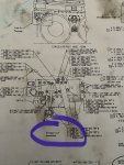
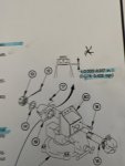
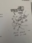
Photos of the schematics and part #’s. No where in the TM did it mention relocating the axle vent T fitting.
There is a right & left spacer for the new rear main cross member support. They slid in without difficulty.
Unless you have large washer type shim stock getting the 0.003 - 0.017” clearance on the brass bearing washer might be iffy in some cases (if you have a buffered brass washer for example).
You do not need to “seat” or “crush” this washer then back off the nut like on a wheel bearing. I simply hand tightened it until the pintle would not turn then backed off the nut until I could get the cotter pin in to the hole. There are 2 cotter pin holes offset in the threaded pintle shank so getting within the clearance range is expected.
I did not intend to post so much on this project but hopefully this info will be useful to someone else.
A big THANK YOU to everyone who posted their experience as it certainly helped me!
Attachments
-
 57.2 KB Views: 12
 -
 79.7 KB Views: 12
 -
 186.1 KB Views: 13
 -
 111 KB Views: 13
 -
 99.2 KB Views: 14
 -
 89.9 KB Views: 13
 -
 43.5 KB Views: 13
 -
 36.6 KB Views: 11
 -
 34.3 KB Views: 11
 -
 63.3 KB Views: 9
Last edited:
coachgeo
Well-known member
- 5,220
- 3,553
- 113
- Location
- North of Cincy OH
if you don't have a multi purpose printer (aka- scanner included) maybe a friend or a member here can scan those to PDF so they can be uploaded to the TM section here. I have one if no one near by does. PM me if that is the case.Photos of the schematics and part #’s. No where in the TM did it mention relocating the axle vent T fitting.
There is a right & left spacer for the new rear main cross member support. They slid in without difficulty.
Smart idea! These kinds of things end up getting lost over time so saving them in a central location is the way to go.if you don't have a multi purpose printer (aka- scanner included) maybe a friend or a member here can scan those to PDF so they can be uploaded to the TM section here. I have one if no one near by does. PM me if that is the case.
I have a scanner and can try & get them uploaded later. I’ve tried uploading docs before without success though. I will need help on where in the forum they should be uploaded to.
- 1,814
- 1,523
- 113
- Location
- Orlando, FL
I'd definitely like to see a copy, if you can scan them. If you can't upload them, PM me.Smart idea! These kinds of things end up getting lost over time so saving them in a central location is the way to go.
I have a scanner and can try & get them uploaded later. I’ve tried uploading docs before without success though. I will need help on where in the forum they should be uploaded to.
- 1,814
- 1,523
- 113
- Location
- Orlando, FL
 - 1.jpeg")
 - 2.jpeg")
 - 3.jpeg")
 - 4.jpeg")
 - 5.jpeg")
 - 6.jpeg")
 - 7.jpeg")
 - 8.jpeg")
coachgeo
Well-known member
- 5,220
- 3,553
- 113
- Location
- North of Cincy OH
IGNORE THIS..... I forgot a step will correct in another post
Thank you for your time and efforts. Unfortunately these are images and not as useful. When you get the time please scan them to PDF so they can be enlarged w/out loss of image clarity.
Below is a youtube video on how to scan to PDF.... way more useful to everyone here. In the video it mentions selecting [add a page]. You want to use this so each page of what you have is scanned into what becomes one single document containing all the pages. Then save that whole file as a PDF
Last edited:
- 1,814
- 1,523
- 113
- Location
- Orlando, FL
Even if he scans them to PDF, you will not be able to enlarge without loss of clarity. That is only true if you output a PDF from the original source (e.g. CAD), and that program was able to do so in a vector format.Thank you for your time and efforts. Unfortunately these are images and not as useful. When you get the time please scan them to PDF so they can be enlarged w/out loss of image clarity.
Long story short, all you would get is a PDF of these same images, with no benefits besides convenience of all being in one file. (I tried to combine them into a single PDF before uploading, but Acrobat was getting an error on the image files, and I didn't have more time to monkey with it, so I posted as-is.)
coachgeo
Well-known member
- 5,220
- 3,553
- 113
- Location
- North of Cincy OH
hmmm...... yep..... been awhile..... totally forgot about the have to convert to vector first.Even if he scans them to PDF, you will not be able to enlarge without loss of clarity. That is only true if you output a PDF from the original source (e.g. CAD), and that program was able to do so in a vector format.
Long story short, all you would get is a PDF of these same images, with no benefits besides convenience of all being in one file. (I tried to combine them into a single PDF before uploading, but Acrobat was getting an error on the image files, and I didn't have more time to monkey with it, so I posted as-is.)
I'll have to re-figure out how I've done this before... will get back to you...
Last edited:
Third From Texas
Well-known member
- 2,841
- 6,676
- 113
- Location
- Corpus Christi Texas
Resolution.
If you don't start with a higher resolution, you can't ever get a high resolution.
That said, some image formats (like .bmp) will *retain* higher resolution better than others (where formats like ..jpg will degrade resolution when converted).
If you scan (or take a picture) at higher res, the format you save and share it in will dictate the clarity.
Also keep in mind that embedding images on forums (opposed to "attaching" the files typically crushes resolution to crap for the sake of faster loading times and bandwidth.
PDF files are really just image files that have a means to print and format text on them. Ideally you start with high-res images (ie: ..bmp) and embed those onto the document. That way they can scale/rescale the viewing size and they retain that "crisp, sharp, focused" image.
Bottom line: images used in PDFs are only as good as the resolution they were scanned/created. Higher res = better
Last edited:
coachgeo
Well-known member
- 5,220
- 3,553
- 113
- Location
- North of Cincy OH
drat.... this website reduced the file size..... images are too small to do a worthwhile conversion
@Awesomeness.... since they were emailed to you........ hope you find time to convert the ones you have to vector files.... then to PDF. Much appreciate.
@Awesomeness.... since they were emailed to you........ hope you find time to convert the ones you have to vector files.... then to PDF. Much appreciate.
Last edited:
coachgeo
Well-known member
- 5,220
- 3,553
- 113
- Location
- North of Cincy OH
Yup... usually use "png" myselfResolution.
If you don't start with a higher resolution, you can't ever get a high resolution.
... ...
Third From Texas
Well-known member
- 2,841
- 6,676
- 113
- Location
- Corpus Christi Texas
As a site admin I can remember explaing it to folks back in the day who would load up bmps right off a camera dump. They'd embed dozens of MASSIVE images into a thread and users would scream about how it took 10 minutes for a single page to load over dialup.drat.... this website reduced the file size..... images are too small to do a worthwhile conversion
Good times....
Last edited:
- 114,391members
- 167,272threads
- 2,354,789posts
- 4,085online users