• Steel Soldiers now has a few new forums, read more about it at: New Munitions Forums!

  • Microsoft MSN, Live, Hotmail, Outlook email users may not be receiving emails. We are working to resolve this issue. Please add support@steelsoldiers.com to your trusted contacts.


M1008 - electric setup/glow plugs/loose cable

.Max.Power.

New member
14
4
3
Location
Germany
Hey folks,

being a new 1985 Chevy M1008 owner since Sunday, I got some initial questions.
I am not a mechanic but willing to learn. I also got the TMs but haven'T got through them, yet.
I've structured my post a bit so that you can respond easier.


Topic 1 - voltage/battery
battery setup

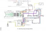
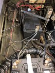
Looking at picture 1 I assume that the car has been converted to 12V as the battery setup is a parallel circuit.
The negative pole of the front bat. (left) is connected to the minu pole of the rear bat. (down) and grounded via the chassis.
Also are the positive poles connected to each other and lead further towards the 'positive terminal junction box'
Following this web page (http://www.chaosboyz.nl/rubriek/techniek/techombouw12v.htm) my configuration looks like their option3 (Convert to two 12-volt isolated systems. One system utilizing the two existing batteries and one alternator. The second system utilizing the other alternator and an additional battery), as I still got both alternators.

Am I right or is the electric completely messed up from what you can see? Can I keep on driving like this?


Engine startup
Most of the time the car starts easily. Sometimes it does not start after the lights went off, somehow if there is not enough power/low bat. but then I just tried 2 or 3 times more and it started without issues.

What could be the reason for this hickup?

Background: The car was not moved a lot the last years but the front bat. is new and I also took it for a 200 mile ride last weekend.
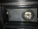

voltage indicator
On pic 2 you can see a voltage indicator. I was already told that this is not an original from the M1008 CUCV but its there - but it does not work. Actually I don't care but I would feel better if it would.

Ideas how to fix or how to connect possible cables?


cigarette lighter
Also not an original feature of the vehicle but useful. At the moment the plus cable is linked to the plus pole of the rear battery. I therefore assume (given it is a 12V setup - as mentioned earlier) that I can pluf in my phone carger or sat nav.

Am I right or will the plugged in device just explode?


Topic 2 - glow plugs
My CUCV has an automatic glow plug system and it seems to work.

Should I leave it like this or change to a manuell one?


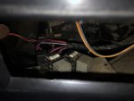
Topic 3 - loose cable
Picture 3 shows a loose orange cable near the glow plug relais.

Where does that belong to?


As mentioned I am not keen on restoring the original state of the car. For my purposes it should just work fine and smoothly.
Hope I can get some info here.


Max


battery setup.jpgvoltage indicator.jpgGlow plug relais (Solenoid) with loose cable.jpg[/U][/U]
 

Attachments

Cory1337

Member
29
28
18
Location
Terre Haute, IN
Welcome!

I agree you look to be converted to 12 volts on the batteries. Do you still have a wire going to the large resistor on the firewall and then from the resistor to the glow plug relay? That is how the factory 24volt system converted to 12volts for the glow plugs. This might be related to your no start issue???

When you have issues starting is it turning over and not firing up, or is it not turning over at all?

If the glow plug card appears to be working I'd keep using it, it's a nice feature to have.

The loose orange wire goes on the top of the Glow Plug Relay. You can see the wiring diagram on E-7(pg952) in TM9-2320-289-34. It is what the Glow Plug card uses to sense the voltage.
 

.Max.Power.

New member
14
4
3
Location
Germany
When you have issues starting is it turning over and not firing up, or is it not turning over at all?
It is not turning over at all, it behaves as if the battery is too weak. Despite that, the third attempt is without any issues - perfect turnover and firing.

Thanks fore the loose wire tip, I’ll attach it this weekend.
 
Last edited:

Cory1337

Member
29
28
18
Location
Terre Haute, IN
It is not turning over at all, it behaves as if the battery is too weak. Despite that, the third attempt is without any issues - perfect turnover and firing.

Thanks fore the loose wire tip, I’ll attach it this weekend.
There is a relay under the dash(middle) that is related to the starter. Check out the doghead relay for more info. Because you are 12v you don't really need to upgrade to the bigger relay, but you might want to test it. If that relay isn't the issue, might be time to get the starter checked out.

Thanks Antennaclimber for fixing my mistake!
 

.Max.Power.

New member
14
4
3
Location
Germany
Hello .Max. Do you know if the truck still has the 24 volt starter.

Are you opposed to going back to 24 volt starting system?
How can I definitivly say that? At least I know that I have 2 alternators. I am not very much into those technical things, yet but I already feel a steep learning curve.

I would not mind going back, but when the current systems works fine I probably would not change it necessarily.
 

cucvmule

collector of stuff
1,139
574
113
Location
Crystal City Mo
Your pictures do help but without seeing in person what has happened it is hard to diagnose on the net. When stock systems are changed it makes it harder to figure out, that is why we go to basics first.
 

cucvmule

collector of stuff
1,139
574
113
Location
Crystal City Mo
Engine startup
Most of the time the car starts easily. Sometimes it does not start after the lights went off, somehow if there is not enough power/low bat. but then I just tried 2 or 3 times more and it started without issues.

What could be the reason for this hickup?
So is the battery off line when the lights go out, no connection?

Not enough power, as Marcus has said in post #8. That will be a starting point to remove any questionable connections that would create problems. Cleaning all grounds that can be removed, cleaned and replaced to make sure a good connection exists. I will verify with volt meter at connection to see that the voltage requirement is there at the connection on both sides.

Hopefully the truck at the moment is not your primary vehicle. Take your time and check circuits methodically.

The starter solenoid and starter will be a 12 or 24 volt unit. It does make a difference.
 

cucvmule

collector of stuff
1,139
574
113
Location
Crystal City Mo
Refering to Training Manuals is always a good self starting point. Then site searching is next but with the different language I am not sure how good that works.

.MAX. as I said we can help but when the primary electrical has changed makes it harder to diagnose and fix but lets get a starting point as in battery connections, grounds eliminated from the equation. Good Luck
 

.Max.Power.

New member
14
4
3
Location
Germany
So is the battery off line when the lights go out, no connection?

Not enough power, as Marcus has said in post #8. That will be a starting point to remove any questionable connections that would create problems. Cleaning all grounds that can be removed, cleaned and replaced to make sure a good connection exists. I will verify with volt meter at connection to see that the voltage requirement is there at the connection on both sides.

Hopefully the truck at the moment is not your primary vehicle. Take your time and check circuits methodically.

The starter solenoid and starter will be a 12 or 24 volt unit. It does make a difference.
The battery is online. I meant when I turn the key one step all the lights which are supposed to go on are functioning well. After a while the glow plug lights (or however they are called) go off and I turn the key further for starting.

The truck is not my primary car, so I can work on it, no probs.

My battery setup is on 12V right now.
As of my knowledge the glow plug systems is always on 12V anyhow (even when the battery is setup for 24V as there is a resistor before the glow plug relais).

I assume my whole system was converted to a full 12V-systems as posted as option 3 here: http://www.chaosboyz.nl/rubriek/techniek/techombouw12v.htm

Strangely enough I do not have a third battery. As for now I also don't know if my starter is a 12V or 24V - I'll ckeck tomorrow.

M1008/M1009 Conversion to Two 12 Volt Isolated Systems

These instructions are a guide to convert the military electrical system of a M1008 or M1009 to two separate 12-volt systems each charged by a single alternator. The passenger side alternator will be used to charge both of the vehicle's batteries. The driver side alternator will beused to charge a battery on an auxiliary system.

Disconnect the ground wire from the negative (-) terminal of the front battery.

Remove the jumper cable that connects the front battery's positive (+) terminal to therear battery's negative (-) terminal. Cut the 8 gauge red wire from the rear batteries negative (-) terminal. This wire will be used in the next step.

Add a 1/4 inch ring terminal to the 8 gauge red wire that was cut in the previous step and replace the terminal on the fusible link end with a 5/16 inch ring terminal. Reinstall the wire attaching the fusible link end to a post on the positive (+) terminal junction block the other end connects to the larger stud on the 12-volt junction block.
motoransicht-B-seite7.jpg (24347 bytes) motoransicht-C-seite8.jpg (26614 bytes)

With the air cleaner removed, remove the resistors located on upper center of the firewall. The resistors are mounted on the backside of black sheet metal mounting bracket. Three hex head screws mount the sheet metal bracket to the firewall. Remove these to access the resistors.

An 8 gauge wire connects the positive (+) terminal junction block to the resistors. Another 8 gauge wire connects the resistors to the glow plug relay. Disconnect these from the resistors. Remove the wire that runs from the resistors to the glow plug relay. Extend the wire that runs from the positive (+) terminal junction block to the resistors so that it is long enough to reach the glow plug relay (insulate the splice). Caution: A new wire may be used to replace the existing wire but the existing wire has a fusible link at the end for short circuit protection. If a new wire is installed, short circuit protection should be installed as close as possible to the end connected to the positive (+) terminal junction block.

Disconnect the wire from the ground terminal on passenger side alternator, insulate the end, bend the wire back, and secure it to the harness. This is an 8 gaugered wire with a white tracer. (The tracer may be hard to locate).
motoransicht-D-seite9.jpg (22724 bytes)

Add a ground wire from the ground terminal of the passenger’s side alternator to the engine.

Remove the condenser mounted to the rear of the passenger’s side alternator. This is the cylindrical part with one wire.

The two alternators are connected together at the 12-volt junction block. The two red 8 gauge wires come together into one ring terminal on the larger stud of the 12-volt junction block. (On the unit done by REC, these wires had blue fusible links on the end.) Disconnect these wires from the 12- volt junction block.

On the smaller stud of the 12-volt junction block, a red 14 gauge wire is attached. (On the unit done by REC, this wire had a brownish-orange fusible link on the end.) Disconnect this wire from the 12-volt junction block.

Connect the wires removed in the two previous steps to a 50-amp circuit breaker/fuse mounted close to the 12-volt junction block. The terminals of this circuit breaker/fuse need to insulated or isolated from accidental contact when working in engine the compartment breaker/fuse as the auxiliary system charging wire.
motoransicht-E-seite9.jpg (24355 bytes)

Connect the auxiliary system charging wire (8 gauge wire minimum) to the other terminal of the circuit breaker/fuse. This wire should run back to a second 50-amp circuit breaker/fuse near where a third battery is to be mounted. The terminals of this circuit breaker/fuse need to insulated or isolated from accidental contact.

A power supply wire (8 gauge minimum) to an auxiliary fuse panel can be attached to same terminal of either 50-amp circuit.

Add a wire (8 gauge minimum) to connect the open terminal of the second circuit breaker/fuse to the positive (+) terminal of the third battery.

Remove 24-volt starter and replace with 12- volt starter. The starter is shimmed for proper gear engagement the replacement starter may require different shimming.

Connect the positive (+) terminal of the front battery to the positive terminal of the rear battery. (Use 4 gauge wire minimum.) The positive terminal of the rear battery should still be connected to the positive junction block.
motoransicht-F-seite10.jpg (23312 bytes)

Ground the third battery to the chassis. (Use 4 gauge wire minimum).

Ground the rear battery to the negative (-) terminal junction block. (Use 4 gauge wire minimum).

Reconnect the ground wire to negative (-) terminal of front battery.
 

Cory1337

Member
29
28
18
Location
Terre Haute, IN
This one?
I believe it is next to those relays.

Here is the doghead relay mod post. It will show you what the original looks like.
 

cucvrus

Well-known member
11,274
9,601
113
Location
Jonestown Pennsylvania
I believe it is next to those relays.

Here is the doghead relay mod post. It will show you what the original looks like.
Don't go hacking into the system till you figure out what the problem is. These mods are not the cure all to a minor issue like a loose or burnt connection. Stick with the plan and find the issue. The batteries and battery cables are the first place I would go and do replacement. the cables you have pictured are poor at best. Good luck. The more you modify the deeper the issue will get when trying to figure out the next issue.
 

Cory1337

Member
29
28
18
Location
Terre Haute, IN
Don't go hacking into the system till you figure out what the problem is. These mods are not the cure all to a minor issue like a loose or burnt connection. Stick with the plan and find the issue. The batteries and battery cables are the first place I would go and do replacement. the cables you have pictured are poor at best. Good luck. The more you modify the deeper the issue will get when trying to figure out the next issue.
I am suggesting the OP check this relay, and using the doghead as a reference to where it is located. In my opinion battery cables do not explain a no start twice and randomly start 3rd time. Sounds more like a faulty relay to me.
 

cucvrus

Well-known member
11,274
9,601
113
Location
Jonestown Pennsylvania
loose battery connections can do it every other time or once a month. As long as it can arc and catch its good. No arc and its done. Start at the top and work your way back. Batteries and connections are the main supply routes for power. From that point I can't see what I am working on so it is a crap shoot. Who has cut what and what has been neglected in the 35 years of service. Good Luck.
 
Top
AdBlock Detected

We get it, advertisements are annoying!

Sure, ad-blocking software does a great job at blocking ads, but it also blocks useful features of our website like our supporting vendors. Their ads help keep Steel Soldiers going. Please consider disabling your ad blockers for the site. Thanks!

I've Disabled AdBlock
No Thanks