- 364
- 266
- 63
- Location
- Myakka City, FL
Fellows,
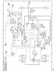
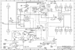
I really am trying to learn how to read the WorkShop Manuals/ once I find he information I have no problem but finding the information is very trying at times, like most of the time/ I am looking for the Air Line and Valve diagram, a schematic that shows the basic position in the frame and the flow of air from origination to application and exhausting.
Now I think I know that the Manuals ending in 10 are Operator Manuals/ The ones ending in 20 WorkShop Manuals/ The ones ending in 24 Parts Manuals/ Still haven't figured the 34's, they seem to be a Advanced WorkShop Manuals?/
Is the air schematic like the wire schematic, that you find it in the end of the chapter? but which chapter?
I have never been noted for my great powers of observation but I just spent the last couple of hours and if I didn't have y'all to turn to I would keep looking but if you could help me out I'm sure that there are others that would benefit besides me but if I'm the only one that does then I ask for your kindness and help me out.
Thank you and Happy Thanksgiving
Lugnuts


