• Steel Soldiers now has a few new forums, read more about it at: New Munitions Forums!

  • Microsoft MSN, Live, Hotmail, Outlook email users may not be receiving emails. We are working to resolve this issue. Please add support@steelsoldiers.com to your trusted contacts.

M37 Restoration Project - Revived

ab705

Active member
55
165
33
Location
Maine
While I'm waiting for some light parts to arrive (red full-lens doors are on back order, amber being shipped), I thought I'd turn my attention to wiring for a while. I have a reproduction wiring harness (the most complicated one), which I bought several years ago, and I just checked on prices for the other harnesses, and I think I'll make up what I need from scratch. I'll stay with the original Douglas connectors when it's expedient to do so, but I'm sure that I'll be making up some Packard connectors as well, at least for certain modifications.

Here's the wiring harness that I already have:
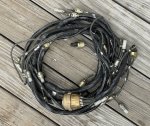
reproduction-wiring-harness-1-smaller-image.jpg

I should be able to use what's left of the remaining old harnesses as general templates for making the new ones. There will be a few modifications, such as for a keyed ignition switch, brake system failure warning lights, 'possibly' electric wipers (haven't decided yet), etc.

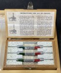
In any case, I want to do a proper job crimping the Douglas 'bullet' contacts (terminals), and I wasn't happy with my existing assortment of crimp tools, so I shopped around a bit and got a good deal on a very nice Buchanan 10692, mil spec MS3191-1 crimp tool kit, which, from what I've heard, should work with these contacts. It's in nearly-new condition (just a bit of patina and NO rust) and still in its original wooden case, complete with three go/no-go gauges, instructions, and even a warranty registration card (I suspect that the warranty may no longer apply, as I think this was probably made in the 1960s). I also have all three positioners (aka, locators) for the three wire size ranges the tool was designed for, which control characteristics such as crimp depth and ratchet release point.

I believe that if this kit works for the Douglas connector contacts, it should also work for the Packard female connectors (i.e., male contacts).

As to the Packard male connectors (with the female contacts), I'm still looking for the best crimper. I've seen people use a 4-indent crimp tool like the above, but I'm not sure if that's optimum for the female contacts in the male connector. I'm guessing that a 'nest and indent' crimper might work well, based on the way the contact is constructed. I'll do a bit of research, but if anyone knows the answer, please chime in...and feel free to correct any of my nomenclature.

Here's the nice wooden case the tool came in:
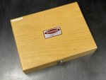
ms3191-1-wooden-box-smaller-image.jpg

And here are the contents (going by the instructions, I think this is a complete kit, and the extra holes are just for future expansion/options):
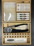
ms3191-1-case-with-all-contents-smaller-image.jpg

Go/no-go gauges:

ms3191-1-go-no-go-gauges-close-up-smaller-image.jpg

The crimp tool with all three positioners.
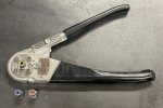
ms3191-1-with-yellow-positioner-smaller-image.jpg

I'll post a few photos after I start using the tool. That might have to wait a few days, as I'm currently trying to get ready to put our dock in the water for the season. I have to pull it out every year before the river freezes over, and because of its design and the nature of our shoreline, it's always a big job to get it back in the water. More later.
 
Last edited:

M813rc

Well-known member
Steel Soldiers Supporter
4,235
3,318
113
Location
Near Austin, Texas
I believe that if this kit works for the Douglas connector contacts, it should also work for the Packard female connectors (i.e., male contacts).

As to the Packard male connectors (with the female contacts), I'm still looking for the best crimper.
It should work for both Douglas and Packard pin connectors, as they appear to be identical. I have found that a Douglas pin, with the metal shroud not in the way, will plug directly into the Packard socket. I haven't looked closely at the Douglas socket side to see how they compare.

My crimper (4-point) works on both the male and female connectors.

Cheers
 

ab705

Active member
55
165
33
Location
Maine
It should work for both Douglas and Packard pin connectors, as they appear to be identical. I have found that a Douglas pin, with the metal shroud not in the way, will plug directly into the Packard socket. I haven't looked closely at the Douglas socket side to see how they compare.

My crimper (4-point) works on both the male and female connectors.
Just guessing, I'd say that there might be multiple crimp types that would work for the 'male' Packard connectors with what I would call a female terminal.

I was just looking at the Amerline Enterprises website page for the MS27144-1 Packard 14 gauge 'male' connector kit, and there is a link to "Tooling Recommendations for Crimping MS Single Wire Series Terminals." If you click on that link, this is part of what comes up:

1717193633455.png

I'm not sure (I'll have to look it up again), but I think that 8338564 is the ordnance number for the terminal used with the MS27144-1 kit. Here's a link to the Y6275 die set. We're talking big bucks unless one can find a good deal on a used die set.
 
Last edited:

ab705

Active member
55
165
33
Location
Maine
The taillight repair kits from Army Jeep Parts arrived yesterday. They look good, and I think they should work well. One had been sprayed with cosmoline (or something similar) as a preservative and had to be cleaned, which was easy enough to do. I plan to paint/touch up the divider plates in white before installing.

light-repair-parts-smaller-image.jpg

For mounting the kits inside the light housings, I obtained some new rubber grommets (for what I assume are vibration-isolating mounts) and made some thick-wall copper grounding sleeves to go inside the grommets, which originally had thin-wall brass rivets inside them. More photos to come when I have time to work on the lights.

I also ordered 200 feet of M13486/1-5 14-gauge wire.
 
Last edited:

ab705

Active member
55
165
33
Location
Maine
I've made a bit of progress on the light restoration work.

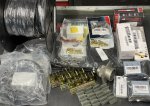
I've started stocking up on supplies for working on the lights and wiring:

supplies-1-smaller-image.jpg

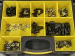
Supplies also include a bunch of Douglas and Packard connectors for both 14- and 12-gauge wire. I have 200 feet of the correct mil-spec 14-gauge wire, and I plan to order a smaller quantity of 12-gauge mil-spec. The thick wire insulation provides a large enough outside diameter for the rubber parts of the connectors to seal snugly against the wire insulation.

supplies-2-smaller-image.jpg

After blasting and priming the light 'cans,' I painted the insides white with the idea of increasing light output a bit. I installed NOS internal parts in two of the lights. For the other two, I salvaged a couple of newer-style internal parts from a couple of used lights that somehow had never leaked over the years, so those parts actually looked newer than the NOS parts.

One of the lights (below) is shown with NOS internal parts installed. The parts are a bit tarnished, but not rusty. The parts came without the rubber shock-isolation grommets, so I installed red silicone grommets with internal zinc-plated brass spacers inside the grommets to make the grounding connections.

light-with nos-internal-parts-smaller-image.jpg

One of the lights (below) is shown with a set of the used (but like-new) internal parts installed. The internals are a bit different from the original ones I found in my lights, as they use a somewhat different shock-isolation design, but just eyeballing it (I plan to measure it to double-check), the bulbs seem to be in the same positions as the originals, so I don't think there will be any functional/performance difference.

light-with-used-but-like-new-internal-parts-smaller-image.jpg

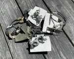
I also worked on some of the light mounting brackets. The photo below shows the right-rear bracket. It was solid, with only a little surface rust, but rather bent up, and the Douglas connector clips were toast. I dismantled those parts and straightened them (not shown).

m37-right-rear-tail-light-bracket-before-smaller-image.jpg

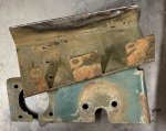
The next image shows the left-side light bracket parts after removing a welded-on license plate holder and straightening the bent parts, but prior to prep and paint work.

m37-left-rear-tail-light-bracket-after-straightening-smaller-image.jpg

The following photo shows the above light brackets and a few other parts after straightening, blasting, priming, and painting:

m37-light-brackets-after-painting.jpg

I have amassed an assortment of light 'doors.' These include a few NOS doors, a couple of good used doors, and a nice repro door. Whichever ones I end up using will be prepped and painted matching Marine Corps green.

m37-light-doors-smaller-image.jpg

I also obtained a couple of amber Gama Goat doors/lenses. I have a pair of red ones on order.

gama-goat-amber-doors-lenses-smaller-image.jpg

Among the supplies I've ordered are a number of 24V LED red and amber bulbs in a few different variations in size, LED patterns, etc. I plan to experiment with these LED bulbs (and the original incandescent bulbs) in combination with the stock doors/lenses and the Gama Goat lenses to see which combinations appear better to me in terms of brightness, beam pattern, viewing angle, etc.

Cheers
 
Last edited:

ab705

Active member
55
165
33
Location
Maine
Very busy this week with other stuff, but some minor progress on the M37:

I bought a replacement Signal-Stat 600 turn signal switch/lever that matches the old corroded one that had been installed in my M37 except for the paint color, which is easy enough to change. The switch appears to be an NOS item, as there are no signs of it ever having been installed. I also received the two red Gama Goat tail light lenses that I ordered (as mentioned previously).

signal-stat-600-smaller-image.jpg

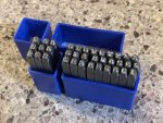
In preparation for duplicating the information from the old data plates onto a new set of reproduction data plates, I bought a set of Capri 1/8-inch number and letter stamps. They appear to be good quality, and the side of each stamp is engraved with its character, making them more user friendly. It would be nice to have a holder for them with some space between the stamps for easier extraction, but that's a minor detail, as I probably won't be using these very often. And besides, space is at a premium in my shop, so the more compact the tools, the better.

character-punch-set-smaller-image.jpg

I also just ordered a turn signal flasher that should work with LED lamps, and a connector for it.

Progress may be slow on the M37 for the next couple of weeks, as the excavation work for our new driveway and garage is supposed to begin soon.
 
Last edited:

G744

Well-known member
Steel Soldiers Supporter
1,725
3,885
113
Location
Hidden Valley, Az
Another tip for any & all: When using threaded stainless hardware, it is wise to coat the screw/bolt threads with milk of magnesia as an anti-seize. Works better than the black goop.
 

ab705

Active member
55
165
33
Location
Maine
Another tip for any & all: When using threaded stainless hardware, it is wise to coat the screw/bolt threads with milk of magnesia as an anti-seize. Works better than the black goop.
Interesting comment. I've used unflavored milk of magnesia (primarily magnesium hydroxide) some years ago to help prevent galling of stainless fasteners in a few high-heat applications.

I use anti-seize compounds on a case-by-case basis, and if I do use an anti-seize compound, I allow for the applicable lubricity factor ("K" factor, or torque coefficient) for torque adjustment. One high-temp anti-seize compound that I use quite a bit is Loctite LB 8036. For other applications, such as spark plugs, I might use a dab of electrically conductive metal-containing compound (copper, nickel, etc.) of which there are several available (but don't get any of the compound on the porcelain insulator of the spark plug).
 
Last edited:

ab705

Active member
55
165
33
Location
Maine
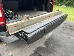
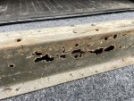
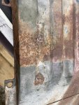
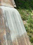
My 1954 M37 is amazingly rust free, but there are a couple of places that tend to rust out on these beasts. One of those places is the front bed-support cross-member, which collects dirt and water, leaving the cross-member perpetually filled with mud. Here's the rusted cross-member:

IMG_2130.JPG

IMG_2132.JPG

I was all set to start fabricating a new cross-member, but then I spied a reproduction cross-member at Midwest Military for what I thought was a reasonable price considering the work involved, and it frees me up to do other restoration tasks that are more interesting.

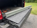
Below is the new cross-member after relieving the sharp edges with a sanding block (to hold paint better), thoroughly scrubbing it with mineral spirits and acetone, and priming it with self-etching primer. I always insert temporary bolts into nuts or threaded holes before painting to keep paint out of the threads.

IMG_1796.JPG

IMG_1798.JPG

After I took the above photo, I painted the cross-member Marine Corps green (no photo) and it's now drying.

Now, some repairs:

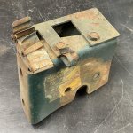
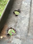
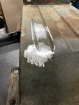
Today, I repaired some 'drain holes' in the floor of the under-bed tool box. I'm guessing that these drain holes were added to the bed and tool box by a soldier in the field with whatever tool that was at hand, and in this case, I suspect that the handy 'tool' was something like an M1 Garand or perhaps some later model.

IMG_2125.JPG

IMG_2127.JPG

First, I closed up the holes a bit with a hammer and dolly:

IMG_2129.JPG

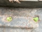
Then I cleaned the area around the holes, welded them shut, and ground them. Here are a couple of the welded-up holes after rough grinding:

holes-after-welding-and-rough-grinding-smaller-image.jpg

And then a coat of temporary primer, just to check the repaired surface:

holes-after-rough-grinding-and-temporary-primer.jpg

The next step is to repair a damaged mounting flange on this piece, and then abrasive blast it. I'm currently looking around for a local blasting company. I have a small blasting cabinet, but this is way too large for it. I do have a wet-blasting attachment for my pressure washer, but it's very messy to use, although I'll resort to that if I can't find any reasonably priced local sandblasting services.
 
Last edited:

ab705

Active member
55
165
33
Location
Maine
It turns out that for duplicating the stamped characters on a replacement main data plate, it appears that I will need 3/32" letter/character stamps instead of 1/8" stamps, so I just ordered a set. I've also been trying to locate an accurate reproduction main data plate. Not much luck so far. I may have to make my own. I should be able to duplicate the layout used on 1954 data plates, which has slightly different fonts from the earlier (e.g., 1951, 52) plates.
 

John Mc

Well-known member
218
305
63
Location
Monkton, VT
Vintage Power Wagons appears to have two different Main Data Plates for the M37 (the description for one of them says it's for the M37B1). I can't tell a difference between the two, but I did not look all that closely.


ab705

Active member
55
165
33
Location
Maine
Vintage Power Wagons appears to have two different Main Data Plates for the M37 (the description for one of them says it's for the M37B1). I can't tell a difference between the two, but I did not look all that closely.
Thanks for the links, but the original 1954 M37 main ID plates (at least the ones that I've seen) have all upper-case characters, rather than a mix of upper- and lower-case characters. If someone has an original main ID plate with mixed upper- and lower-case characters, please post a photo of it.

I also want to make sure that the black areas of the plate are recessed slightly (probably etched?) into the aluminum. Some of the reproduction ID plates I've seen are just ink or paint silkscreened onto the aluminum surface.

Years ago, I bought a very nice set of reproduction data plates that included an excellent main ID plate, but I can't seem to find them anywhere. :(

I'll keep looking through my stuff as well as online, but if I can't find one I think it might be fun to try making a reproduction plate myself. I should be able to create a reasonable facsimile with Adobe Illustrator, InDesign, etc., based on photos of original ID plates. If someone could post or PM a clear, direct photo of their original main ID plate, preferably a 1954 or maybe 1953 version, that would be helpful, as most of the photos I've seen online are not the best quality.
 
Last edited:

ab705

Active member
55
165
33
Location
Maine
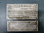
I guess you are right. I just found the picture of the data plate on my 1951 M37. It's all caps:
Actually, I think some M37s may have had original data plates like that one from VPW. I just haven't seen an original plate of that type in person...yet. I'm going to do a bit of research on the topic and see what I can find out, since I'd like to have a plate that is appropriate for my 1954 M37.
 

mobiledab

Member
Steel Soldiers Supporter
Al,

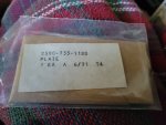
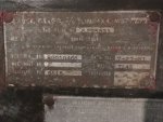
Found these last night on FB M37/M43 Group. Don't know if they help, but thought I'd send along just in case. One from 1953, another from 1954, and a third NOS in USG packaging. Maybe a modification in style/fonts for -B1 series? Anyway, hope they help. Will pass along any others I come across.

David
 

Attachments

ab705

Active member
55
165
33
Location
Maine
Found these last night on FB M37/M43 Group. Don't know if they help, but thought I'd send along just in case. One from 1953, another from 1954, and a third NOS in USG packaging. Maybe a modification in style/fonts for -B1 series? Anyway, hope they help. Will pass along any others I come across.
Your pictures of the 1953 and 1954 plates look correct for original plates, as far as I can tell. I'm just guessing that your photo of the NOS plate with upper- and lower-case text shows what might have been intended as a replacement plate, but more research needed.

There were situations where an original data plate was supposed to be removed, such as when an M37 was converted to an M42 Command Truck with the installation of a command kit, which sometimes included radio equipment, and when the command kit was removed, I believe the instructions said to remove the M42 plate and put an M37 plate back on. If the original M37 plate had been lost, then I'm assuming that some kind of replacement plate would have to be available. That apparently was the case with my M37. The replacement plate that was installed when it was re-released as an M37 was more like the original plate in your 1953 or 1954 picture, except that the black background was anodized instead of etched like the original.

Anyone, feel free to chime in. I'm here to learn as well as share.
 

ab705

Active member
55
165
33
Location
Maine
Back to work on the M37 this week.

I've just started restoring the headlights. I blasted, primed, and painted the brackets that mount the headlights on the fenders, as well as the zinc/pot metal brackets that go under the headlight bodies.

I just received a set of replacement rubber headlight mounting grommets today and installed them in the headlight brackets. I would NOT say that they were fun to install, as they had to be squished with considerable force to start them in the holes. Once started, they slid in fairly easily until the bracket snapped into the groove in the grommet. I managed to insert them with no tools other than my fingers and a little grease, but my fingers are a bit sore. I'm sure it helped that the rubber was reasonably pliable. I also left the whitish waxy storage coating on them, as I figured it added a bit of lubrication for installation. I'll clean it off later.

headlight-brackets-and-grommets.jpg grommet-headlight-bracket.jpg
 
Last edited:

mobiledab

Member
Steel Soldiers Supporter
Back to work on the M37 this week.

I've just started restoring the headlights. I blasted, primed, and painted the brackets that mount the headlights on the fenders, as well as the zinc/pot metal brackets that go under the headlight bodies.

I just received a set of replacement rubber headlight mounting grommets today and installed them in the headlight brackets. I would NOT say that they were fun to install, as they had to be squished with considerable force to start them in the holes. Once started, they slid in fairly easily until the bracket snapped into the groove in the grommet. I managed to insert them with no tools other than my fingers and a little grease, but my fingers are a bit sore. I'm sure it helped that the rubber was reasonably pliable. I also left the whitish waxy storage coating on them, as I figured it added a bit of lubrication for installation. I'll clean it off later.
View attachment 928886 View attachment 928892
You do first class work! I just need to hire you to work on my truck! Your M37 is going to be not only beautiful, but functionally superior when you are done!
 
Top
AdBlock Detected

We get it, advertisements are annoying!

Sure, ad-blocking software does a great job at blocking ads, but it also blocks useful features of our website like our supporting vendors. Their ads help keep Steel Soldiers going. Please consider disabling your ad blockers for the site. Thanks!

I've Disabled AdBlock
No Thanks