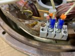
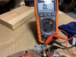
Well, hopefully Guy will check the new readings tomorrow, but right off the bat, the F1 to F2 resistance looks like a problem. Those are your Field excite wires which if there is an open circuit , there is no way the regulator can excite the field to create any power.
Indeed. This is a no go. The two wires go to a coil inside the Gen head, (in army talk, Main Gen) to light off (excite) the main gen. An open indicates a break someplace in the circuit.
Test #5, is a no go. T2 & T5 are a pair. They go to a coil in the main gen. An open indicates a break someplace in the circuit.
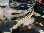
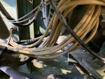
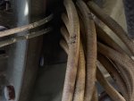
Not good. But don't jump from the bridge with your pockets full of rocks yet. Take the plugs apart. look for loose or broken wires. Normally when a wire BREAKS, its within 5-7 cm of the ends of the wire/cable. An old trick is to run the wire between your hands, or better yet, fingers. Back and forth. If there is a break, you can often FEEL it.
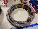
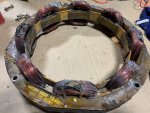
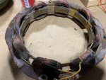
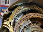
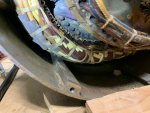
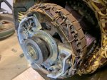
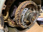
Failing that, you can open up the main gen. take it out. Put it on a CLEAN table and start opening it up. Look for loose wires, and broken/burnt wires. Trace your problem wires to the source.
If you find nothing, you have two options. Rewind the thing, and I can not tell you what that cost in the States. Maybe Ray can. Or, simply find another main gen.
If you go for a rewind, ask around. Ask around for peoples opinion about the shop. Ask the shop if they want to pull the stator coil pack or if you have to. Its not hard, but you got to be earful. Best is if they do it, because if they screw it up putting it back in, they have to fix it. Like I said, not hard to remove. You basically need a flame thrower and a nice hammer.

 But he said the stator was replaced already so that would tell me to look at the wires on the plug. It may have just been a bad plug all along? I seems to me that this set had an issue that they tried to fix and when they couldn't it went out for auction. So I would eliminate the parts that were replaced and concentrate on what is left that is testing bad. You guys are so far ahead of me now I have no idea what tests are what but are any of those tests covering stuff that was not replaced in the repair?