• Steel Soldiers now has a few new forums, read more about it at: New Munitions Forums!

  • Microsoft MSN, Live, Hotmail, Outlook email users may not be receiving emails. We are working to resolve this issue. Please add support@steelsoldiers.com to your trusted contacts.

MEP-002A, will Start, Run then dies....any suggestions?

Scoobyshep

Well-known member
1,239
1,789
113
Location
Florida
Okay...short version; Found the "PC" mark and its hash mark, turned the flywheel so the timing pointer was on the "PC" hashmark, 1/8" bit moves freely in and out of the IP's timing port and alignment hole of the face gear...Done. Ready to remove...YES??

Longer version:
I put an 1/8" bit into the timing hole on the side of the (still mounted) IP and began slowly turning the flywheel while applying lite pressure to the bit until I could feel the bit drop into the face gear...I look into the timing port on side of flywheel housing and nothing, no "PC" mark just rust. I put a Sharpie mark on flywheel at the pointer and repeated the process. This time when the bit dropped it the face gear, I looked into the timing port and could see the Sharpie mark was just below the pointer and while shining a flashlight at varying angle I caught a glimpse of a C. With some careful, light scraping of the rust using the flat bottom edge of a screwdriver, Carb clean and compressed air I was able to clean it enough to clearly see the "PC" mark and corresponding yellow hash mark...BINGO!...I also added a mark with a silver, oil based, paint pen on the left side of the P and in line with the "PC" hash mark to hopefully make it easier to find in the future.

Next, just to confirm, I removed the drill bit, turn the flywheel, then repeated the above process and the drill bit dropped into the face gear hole at or about the corresponding "PC" mark on the flywheel. With the drill bit still in the face gear I very slightly and very gentle moved the flywheel clockwise and counter and noticed the dill bit would start to tighten up about 1½ to 2 hash marks below the "PC" hash mark and about 1 to 1½ hash marks above the "PC" hash mark...I'm guessing that these "spaces" above and below the "PC" mark account for the "slightly opening-fully opened-slightly closed-fully closed" positions of the output valve of the IP...again just my guess. You guys feel free to correct me and/or elaborate.
View attachment 939545 View attachment 939546 View attachment 939548
So, that's it thus far. I will pull the IP tomorrow afternoon unless I hear from you guys to the contrary.
The additional hash marks are for timing the button with the flow method those tell you how many button sizes you need to go bigger or smaller. Sounds like you found the timing groove in the gear so yes you are ready to remove it
 

1FAST4

Member
86
99
18
Location
NorCal
So, here's what I got done today along with some Pic's and a couple of questions:
20250123_163112.jpg

First look at IP.
20250123_162913.jpg 20250123_162951.jpg 20250123_163014.jpg 20250123_163032.jpg

First look at Injector Nozzles.
20250123_152440.jpg 20250123_152459.jpg 20250123_152518.jpg 20250123_152527.jpg

Nozzle holders.
20250123_152157.jpg 20250123_152210.jpg

Cam lobe position. Three shims...not just one, this normal?
20250123_155457.jpg 20250123_155745.jpg

Nozzles lightly cleaned with some Diesel. I don't see items 7, 8 or 9 as shown in the TM, I'm I missing them?
20250123_170114.jpg 20250123_170050.jpg 20250123_170117.jpg
Nozzle & Holder Parts.jpg

Let me know your guy's thoughts on the Shims and missing...or not missing items for the nozzles.

The aluminum "Fin" adapter that goes on the Nozzle must be corroded because I can't get them off the nozzles, soaked them with Knocker Loose Plus and we'll see how they do tomorrow; they'll turn slightly mounted in the vise and tapped with a Dead Blow (lightly and not on the fins).

I'm going to try to get into the IP this weekend.
 

Ray70

Well-known member
Steel Soldiers Supporter
2,707
6,378
113
Location
West greenwich/RI
Cam lobe is correctly positioned at PC on #1 compression stroke.
As for the "missing items" you aren't missing them, I believe they are still inside the head.
The 3 parts are a large dia., thin copper ring, then a 3/16" thick steel disc, then a thin fiber sealing washer.
The copper rings and steel discs are probably stuck in the head still, while the fiber washer may have torn apart and is now partially stuck to the injector and partially stuck to the steel disc that is still in the head.
These parts can be purchased as a kit or individually. the PN's are listed in the -24P TM
On the injector heat sinks, they tend to get frozen onto the injector body quite often.
I use a MAPP gas torch to heat the finned heat sink and expand it, then get a screwdriver between the heat sink and injector body to pry it off.
heat + penetrating oil can help too.
 

1FAST4

Member
86
99
18
Location
NorCal
Cam lobe is correctly positioned at PC on #1 compression stroke.
As for the "missing items" you aren't missing them, I believe they are still inside the head.
The 3 parts are a large dia., thin copper ring, then a 3/16" thick steel disc, then a thin fiber sealing washer.
The copper rings and steel discs are probably stuck in the head still, while the fiber washer may have torn apart and is now partially stuck to the injector and partially stuck to the steel disc that is still in the head.
These parts can be purchased as a kit or individually. the PN's are listed in the -24P TM

On the injector heat sinks, they tend to get frozen onto the injector body quite often.
I use a MAPP gas torch to heat the finned heat sink and expand it, then get a screwdriver between the heat sink and injector body to pry it off.
heat + penetrating oil can help too.
Should I try to get the Copper Ring and Disc out? Or just leave them and clean the surface of the Disc the best I can; from the looks of the corrosion, I think it may be a quite a chore to get them out. Fiber washers already ordered direct from Cummins, $6 each and no gouging on the shipping cost.

Used your Heat, Penetrating oil and screwdriver method and the finned heat sinks came right off...many thanks!!! I then cleaned the nozzle/holder up with some Diesel and had them tested a local Diesel Nozzle/IP shop; Tech said they both tested fine and where in good shape.

Next post will be about tearing into the IP today and what I see...
 

Scoobyshep

Well-known member
1,239
1,789
113
Location
Florida
Should I try to get the Copper Ring and Disc out? Or just leave them and clean the surface of the Disc the best I can; from the looks of the corrosion, I think it may be a quite a chore to get them out. Fiber washers already ordered direct from Cummins, $6 each and no gouging on the shipping cost.

Used your Heat, Penetrating oil and screwdriver method and the finned heat sinks came right off...many thanks!!! I then cleaned the nozzle/holder up with some Diesel and had them tested a local Diesel Nozzle/IP shop; Tech said they both tested fine and where in good shape.

Next post will be about tearing into the IP today and what I see...
id let that sleeping dog lie
 

1FAST4

Member
86
99
18
Location
NorCal
So today, following the "Ambac 50 Service Instructions" I disassemble the IP and put it in the mounting fixture that I fab'd. Here are some Pic's and a few questions:

Control unit:
Had some staining but overall looked good.
20250125_113901.jpg 20250125_113854.jpg


Delivery Valve:
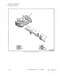
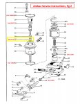
After removal I saw some debris at the bottom but think it was stuck to the rim of the valve assemble and broke free as I was pulling everything out; But one thing that I'm NOT seeing is the "Delivery Valve Spacer". Item #35 on Pg 2 of the Service Instructions. Is it there and I'm just not seeing it?
20250125_115121.jpg 20250125_115358.jpg 20250125_115551.jpg 20250125_120654.jpg Delivery Valve Spacer.jpg

Hydraulic Head:
Remove the Button, Plunger Retaining Rings (easy with Ray70's C-clamp tool) and pulled everything out and what did I see?...Wait for it... the Plunger Guide was cracked. When I went to remove Gear Retainer and Face Gear the whole thing came apart and the Plunger Guide fell out, not just cracked but completely broken into two pieces...Hum, you guys think this could be the problem?
20250125_135029.jpg 20250125_140059.jpg

The Plunger had some slight marring where the Plunger Guide would normally rest but otherwise looked great and moved freely up and down into the head and Metering Sleeve. What is the correct orientation of the Plunger when reassembling? Or is it automatically orientated with the Plunger Guide? I wasn't paying attention to either when I removed them...
20250125_142320.jpg20250125_142332.jpg

Same orientation question on the Metering Sleeve..."Dot" facing up or down, towards the Blower or away from it?
20250125_142259.jpg20250125_142249.jpg

Everything is now soaking in Acitone...I ordered a gasket "rebuild" kit (KT85166) and Plunger Guide from GMG last week in anticipation; should be here next week, hopefully,

So, that's all I got for now...look forward to hearing what you guys think.
 
Last edited:

Ray70

Well-known member
Steel Soldiers Supporter
2,707
6,378
113
Location
West greenwich/RI
The delivery valve spacer is there,,,, barely! The blackish remnant of a paper thin plastic ring you see on the delivery valve holder is the spacer!
It is a very thin useless piece of $50 plastic that simply helps hold the delivery valve in place while assembling the IP. It is helpful when working on an IP while mounted to the motor, but when working vertically in a vise it it totally useless and a waste of $50 for a new one.
I would just clean out the pieces and forget about it!
 

Ray70

Well-known member
Steel Soldiers Supporter
2,707
6,378
113
Location
West greenwich/RI
The plunger guide will set the orientation of the plunger. The guide only goes on in 1 orientation ( plunger has 3 flat sides and 1 curved side ) and the guide is marked which face goes up. Same with the metering sleeve. goes in with the dot facing up. By UP they mean towards the tip of the plunger ( see figure 6A in the Ambac manual )
 

Dog Breath

Member
Steel Soldiers Supporter
58
81
18
Location
Wisconsin
I am having the same issue with an 002. It will run for 30 seconds or so and then it shuts off with white smoke. Shut off solenoid is not shutting it down so it must be fuel related. I cleaned ip, check valves in fuel pumps, inline check valves and all lines I am thinking maybe a piece of junk is blocking somewhere.
 

1FAST4

Member
86
99
18
Location
NorCal
The plunger guide will set the orientation of the plunger. The guide only goes on in 1 orientation ( plunger has 3 flat sides and 1 curved side ) and the guide is marked which face goes up. Same with the metering sleeve. goes in with the dot facing up. By UP they mean towards the tip of the plunger ( see figure 6A in the Ambac manual )
Sorry, I hadn't made it to the "Reassembly" section until after your Post; I then read it and it is explained very well (read the Manual, read the Manual...).
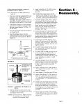
Section 5 -Reassembly

I do have two follow up questions:
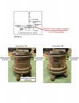
Paragraph 4 and Figure 6A shows and explains the proper orientation of the Metering Sleeve being inserted from the left side of the Hydraulic Head but does not say how or show any "landmarks" on the drawing indicating what orientation the Head should be in before inserting the Metering Sleeve...or does it even matter? ...see the below Pic.
Head orientation for metering sleeve.jpg

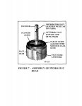
Figure 7 show a "Face Gear Linemark" on the Face Gear; mine does not have that mark or any other marks on the Face Gear. Does that matter?
Face Gear Linemark.jpg 20250126_103828.jpg 20250126_103844.jpg
 

Ray70

Well-known member
Steel Soldiers Supporter
2,707
6,378
113
Location
West greenwich/RI
The orientation of the head before inserting the metering sleeve does not matter. The sleeve just slides up and down on the plunger by way of the throttle assembly's pin. As long as the dot is facing up, nothing else matters.

On the gear line mark, all you need to do is put the plunger guide with the marked face upward and the point on the side of the plunger guide aligned with the small cut out in the gear ( it only fits in this orientation ) and the plunger will only fit into the plunger guide in one orientation.
 

1FAST4

Member
86
99
18
Location
NorCal
The orientation of the head before inserting the metering sleeve does not matter. The sleeve just slides up and down on the plunger by way of the throttle assembly's pin. As long as the dot is facing up, nothing else matters.

On the gear line mark, all you need to do is put the plunger guide with the marked face upward and the point on the side of the plunger guide aligned with the small cut out in the gear ( it only fits in this orientation ) and the plunger will only fit into the plunger guide in one orientation.
Perfect....Thanks Ray!!!!
 
Top
AdBlock Detected

We get it, advertisements are annoying!

Sure, ad-blocking software does a great job at blocking ads, but it also blocks useful features of our website like our supporting vendors. Their ads help keep Steel Soldiers going. Please consider disabling your ad blockers for the site. Thanks!

I've Disabled AdBlock
No Thanks