Isaac-1
Well-known member
- 1,970
- 51
- 48
- Location
- SW, Louisiana
I am trouble shooting a voltage regulation problem (voltage going high, regulator good, no output showing on panel meters) on my MEP-003a and have now reached the point of testing CVT1 per the TM. The instructions in the TM say to measure resistance between H1-H2, H3-H4, H5-H6, and between X1-X3 and C1-C2. My problem is the screw terminals on my CVT do not appear to be marked, does anyone have a diagram showing the relative position of the terminals on CVT1, it does not seem to be in the TM that I can find.
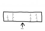
Pattern looks like this:
X X X X
X X X X
X X X
Where I have confirmed by wire numbers that
H1 H2 X X
X X X X
X X X
but am at a loss on some of the others as the wire numbers seem to be missing on H3 and H5 on the control box wiring diagram (I did confirm the the wire numbers on the row below H1 and H2 don't seem to be H4)
On the good news H1-H2 tested in spec.
thanks
Ike
p.s. if anyone has a spare CVT1 for sale please let me know as I am now strongly suspecting it or a wiring issue as my problem


