• Steel Soldiers now has a few new forums, read more about it at: New Munitions Forums!

  • Microsoft MSN, Live, Hotmail, Outlook email users may not be receiving emails. We are working to resolve this issue. Please add support@steelsoldiers.com to your trusted contacts.

MEP 803a governor question

Ray70

Well-known member
Steel Soldiers Supporter
2,903
7,057
113
Location
West greenwich/RI
Something you could try is to 1 by 1 remove the line and injector, reorient it so it's off to the side of the motor and crank it over and observe the fuel spray from each metering pump / injector combo. If you find 1 that doesn't spray when it should or continues to spray after the fuel solenoid is in the off position then you can at least narrow it down to the offending cyl. and investigate further.
When you say the motor won't turn off, does it continue to run at speed or does it die down but just barely continue at a low idle?
If it is staying at speed despite the FSS pushing the lever to the off position, then I would suspect a metering pump pin is not in the rack, or the rack is bent etc. If it idles low and just won't quite shut off You may need to adjust them or adjust the lever stop as Lucky described.
You also want all the metering pumps rotated counter clockwise as far as they will go until the fuel inlet hose is touching the adjacent pushrod tube.
If any pumps are spaced away from the pushrod ( too far clockwise ) that can cause that pump to not quite turn off completely.
Differences in pump orientation can also cause differences in fuel delivery and EGT's between cylinders, so we all typically put all 4 right against the pushrod tubes.
 

rickf

Well-known member
Steel Soldiers Supporter
3,336
2,237
113
Location
Pemberton, N.J.
Seems to me that is inviting an oil leak from a worn through pushrod tube. I would space it away from the tube using a feeler gauge to get the exact same on each one. You only need a few thousandths clearance to prevent abrasion.
 

Ray70

Well-known member
Steel Soldiers Supporter
2,903
7,057
113
Location
West greenwich/RI
Perhaps, but it's rubber touching steel and the part that touches is where the steel nipple of the metering pump is inside the hose, so there is very little chance for any vibration or movement between them, but setting them all with a slight gap would work just fine.
 

LuckeyD

Well-known member
97
281
53
Location
Vilseck, Germany
I read each reply and one member touched on something. In post '13 you state the pumps are new and after a bad experience installing, you state they all worked freely. The member post that started me thinking asked if it tried to slow or just kept running as if nothing was different. So lets talk both.
I asked to pull 1 pump and see if the rack was freely moving. The video helps but the idea was to see if the rack was stuck, bound, or sticking inside. If you move the shut off back and forth you see inside if it moves freely. If this is good I'll ask if the fuel solenoid depowers and pushed the shut off to the no fuel position or does it not budge. Here is why. The solenoid is spring loaded to extend the arm out so it pushed the fuel shut off from the governor to the no fuel position. This shuts the engine off. The solenoid has a common(ground from chassis) and a hold from terminal 3 of the start switch, and a pull from the K16 that is removed after the mag pickup engages the K16 with 2.5-3.5VAC that is applied to the S14 funny looking relay that also flashed the generator field and makes AC production start. Removing 1 pump and looking or feeling if the rack is free and if the solenoid is working correctly narrows what is wrong with your no shut off condition. Let us know and oh, Pages 3-18 thru 3-25 TM 9-2815-253-24 in the forum manuals explains the pumps, the factory settings, and how to measure so you may time the pumps using the shims which are very thin but very important and uses a block enabling you to easily install pumps but again you need to remove the governor gear housing and we all tried to say how to do this without doing that. Not timed correctly causes low power in a new engine thus the gen can not hold a 100% load. Old engines where the rings are not seated yet from oil film build up, rust is another story. So let us know what happens. Cool?👍
 

rickf

Well-known member
Steel Soldiers Supporter
3,336
2,237
113
Location
Pemberton, N.J.
You mentioned you replaced ONE pump? Did you manage to get that other one bent back straight? I would do the test Lucky is mentioning and if one is hanging up that bent one would be the one I pull.
 
Last edited:

SQF

Member
37
7
8
Location
Chelsea, Michigan
Ok all, not sure what I did but two new pumps later it runs great. My only caveat is it shut off slightly slower than our other 803. I will get a video of the shut down and you can tell me if something is still out of whack.

Now on to my next issue. So I can’t get it to energize. When I move S5 up the light comes on but won’t say on. I took the top cover off and I have 24v at K1 x an y. I also hear K1 “click” when I hit S5. After a few minutes playing with it, all the sudden the “hot electrical smell” started. I shut it right down. The engine also was labored all the sudden. Not sure what I did. I let it cool and fired it back up, it ran for 10-15 minutes without issue. Obviously my messing with K1 and S5 did something.

I remember years ago someone giving me a TM link as to where to go from here trouble shooting it. But I can’t find it.

Any advice on where to go now appreciated.
 

Ray70

Well-known member
Steel Soldiers Supporter
2,903
7,057
113
Location
West greenwich/RI
Check the large wires going into and out of K1, especially the ones leaving K1 and going to the lugs. Where the wires bend and go around the corner of the sheet metal they will sometimes wear through the insulation and short to the chassis.
Perhaps K1 was sticking and you freed it up, only to find the output wires shorted to chassis?
 

LuckeyD

Well-known member
97
281
53
Location
Vilseck, Germany
Good Day: There are two issues. The sluggish shutdown, and a main contactor issue as I read your response. Lets talk one at a time.

1. slow shut down- This can be caused by several things, but mainly one injection pump is allowing fuel to get into a cylinder causing a slower shut down. This will also cause issues at high loads keeping the gen running at speed, Frequency with changing loads. Why and the fix is the issue. The pumps are correctly set in their position if you have them in a position where the fuel input is almost touching the push rod tube meaning they should be turned slightly counterclockwise and held in place with the crows foot clamp. just loosen the pump HP output and then loosen the crows foot and use a 17mm to turn the pump if required (pump tops have little notches in them making hand turning a pain)and they should all be the same. Second issue may be one of the pumps is not allowing thee fuel rack to spring back or the spring is failing inside the governor(bent rack, pump tang sluggish, governor spring). third is the stop setting that is adjustable but is plumbed as this is factory set. I have how to set this attached. This is a touchy feely thing as it is set to just before the rack is fully in the no fuel position, like 1-2 bolt flats so be careful please. Lets us know how it goes....

2. Main contactor not staying closed: You may want to look over the other attachments, as this can get hairy for some folks like me. Electrical burning smell and engine slowing concerns me. OK, here is how this thing functions: B+ is from the S1 terminal 3 applied to contacts of the K20 which should be a closed set of contacts if you have oil pressure, providing B+ to the X terminal of the K1 and you also get that on the Y terminal of the K1 and this goes to the S5 terminal 5. The S5 when you ask to close the K1 provides a chassis ground to the DS7 and thru K8 (2 sets of contacts) and thru the piggy back set of contacts in the K1 which when engaged closes those piggy back contacts holding the circuit so the K1 stays closed. You can follow a lot of this with the gen set just sitting there and a multimeter following the circuit from the K1X to the S5 and from Terminal 3 to the K1 terminal 11. S5 Terminal 6 is where the initial ground is applied to the circuit. I used to take the top off the K1 and see if main contacts required burnished and used my finger to push the contacts closed and showed Soldiers how the piggy back contacts worked and you can also use a meter to see they are working or not, which may be your issue.

You may have to check some wiring and S8 connections back to the TB3 and check if they messed with TB3 connections as folks mess with these. I found everyone connected TB3 starting from the inside with T1 to 001A thru T12 to 012A instead of using the wiring diagram (in the FORUM) causing the main gen to fight itself or S8 miswiring. No issues if they did it right. Then I found wiring an S8 seemed to be an issue so I made up the attachment. Seemed to help stupid folks like me as the manual is hard to follow a bit the first reading thru. Look over the attached and try to go thru the thing on the gen. You will have questions so ask please. I am hoping you find K1 bad contacts, bad Piggyback contacts, and a bit of water inside the K1 explaining everything. Let us know how it goes and I'll keep an eye on the email for your questions. Cool?
 

Attachments

Last edited by a moderator:

SQF

Member
37
7
8
Location
Chelsea, Michigan
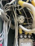
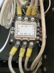
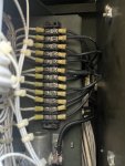
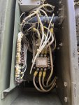
Hey LuckyD, thanks for all the info. Unfortunately I haven't found the "silver bullet" yet. Admittedly, I am a novice when it comes to reading wiring diagrams. I however did find some things of interest. See the attached photos and let me know if anything jumps out at you. Specifically, the crank relay has been messed with and is/was loose (not secured). Also on the TB3 one of the wires was wrapped in electrical tape. When I removed the tape, there is a plastic sleeve around the wire. Not like a heat shrink connector, but a consistent diameter the entire length. Is that factory? Also, on K1, the 21 and 22 terminals are missing nuts and have no wires attached. To the best of my ability, I believe S8 to be correctly wired, but I need to triple check it. In the meantime, do you see anything that screams, "fix me?" Thanks all!
 

Attachments

Guyfang

Moderator
Staff member
Moderator
17,967
26,913
113
Location
Burgkunstadt, Germany
Hey LuckyD, thanks for all the info. Unfortunately I haven't found the "silver bullet" yet. Admittedly, I am a novice when it comes to reading wiring diagrams. I however did find some things of interest. See the attached photos and let me know if anything jumps out at you. Specifically, the crank relay has been messed with and is/was loose (not secured). (Well, first INSURE, by wire number to the proper terminal, that it is wired right. Then secure it to the box.) Also on the TB3 one of the wires was wrapped in electrical tape. (It looks like the wire was repaired. The only way to know is to open it up, or just put your trust in the Lord. I would look.) When I removed the tape, there is a plastic sleeve around the wire. Not like a heat shrink connector, but a consistent diameter the entire length. Is that factory? (NO!) Also, on K1, the 21 and 22 terminals are missing nuts and have no wires attached.

1755986259822.png
Terminals 21 & 22 are not used.

To the best of my ability, I believe S8 to be correctly wired, but I need to triple check it. In the meantime, do you see anything that screams, "fix me?" Thanks all!

I would check each and every wire there, By Wire number against the schematics, because it looks like someone has fooled around in there.

If you are trying to get Daves attention, type: @LuckeyD and he gets a mail alerting him to look see.

If you start this set up, and just let it run at 60 hertz without applying a load, do you get the smokey smell?
 

SQF

Member
37
7
8
Location
Chelsea, Michigan
No, it will run indefinitely without any smell until I start trying to engage K1. Then randomly I get a smell, which obviously leads me to shut it down immediately. Also, when I have the smell, I still have no engagement.
 

LuckeyD

Well-known member
97
281
53
Location
Vilseck, Germany
Sorry Folks, been busy, and took a nap as well. Running hotel PAPA can get a little busy sometimes. Lets do this one at a time,

TB3: That insulation tube is not OEM. There is enough T winding if there is a conductive issue, just crimp a new 20 amp connector on there and discard it. These are NOT soldered as they can heat and melt solder.

K2 start relay: that's a mess with corrosion on the coil connection. When you get the time, disconnect the main Battery negative, and then try cleaning this up. May help.

K1: terminals 21 and 22 are not used, but lock washers and lose hardware on a vibrating gen is not good, so that extra can be removed and saved for the future. Please do the following; check each connected wire by its number on the S8. All of them. Wire numbers are on each wire and they are supposed to be every 15 CM. (No they are not but I wasn't arguing with the engineers) Ensure the S8 is switchable and you do not feel sand grinding inside it. The main load connections to the K1 check to what I sent on S8 wiring guide and if all is good now do this experiment. All off; disconnect and tag each main load terminal coming out of the K1 that goes down to the load terminals. The tag is so You know where they go later. Keep hardware as you will need it later. Make sure those cables are out of the way. Now if the K1 is engaged, you have nothing from the output to touch anything but studs sticking up on the K1. Now, start and power up. Have a meter ready to read AC Voltage, and engage the K1. Any smell? if so can you locate about where? open K1, shut down and investigate. If no immediate smell measure K1 output on those studs. Stud to chassis ground should be 120VAC and each reading should be within 2 V AC of each other and no more than 4 VAC says the Tech Manual. If more than 2VAC check the AC into the K1. Also measure the AC voltage drop across each phase. If you get a loss of 2VAC or more across the K1, you need to work on the K1 contacts as pitted contacts do not make good connections, create heat, sizzle, and get worse sometimes in a real hurry. I even used silver solder and repaired contact pads but you have to burnish them so all are relative the same and polished. Don't connect those load terminal cables yet. No smell before k1 is energized indicated something in the K1 or after. If all the smell was not present, you need to investigate behind the load terminal board. There are filters and caps behind there on each phase. They are used to ensure clean AC Power is delivered to the load on military systems. They remove random spikes, and unwanted phase ripples in the AC wave form. They are not really required for usual utility power and if you look I'll bet one is blackened or busted, or corroded if nothing previous was found. Great if they are there though and working. Give it a go, let us know. Sunday I'll be playing with car with Hotel Papa and Monday I'M looking at a new used car . Mine is 20 years old.
 

SQF

Member
37
7
8
Location
Chelsea, Michigan
Ok, the novice in me is about to shine. So I never looked at the other side of TB3… all but two wires were on the wrong terminals. I thought I found it! I put every wire on the correct terminals. No change.
Next I went to @LuckeyD experiment. Then it occurred to me that obviously K1 is a relay and should (I assume?) have 120VAC at terminals A1,B1, & C1 all the time with the engine running correct? If so I have 4.5VAC, 2.5VAC and .5VAC respectively. So if K1 knows the voltage is no good it obviously will never close, correct? Now where do I go?
Thanks ALL
 

LuckeyD

Well-known member
97
281
53
Location
Vilseck, Germany
Good Day: So you took the S8 wiring Guide and matched TB3 wire numbers T1 to 001A all the way to to T12 to 012A and all those match. Does not matter where on the TB so long the wire numbers match on a particular terminal. Mine on the guide are after RESET, where the fold outs in the Tech Manual are OEM the way they are supposed to be. You have 120VAC on L1, L2, and L3 on the K1 terminals A1, B1, and C1 measured to chassis. You measured across the K1 contacts A1 to A2 and got 4.5VAC; B1 to B2 and got 2.5 VAC, and C1 to C2 you got 0.5VAC; am I correct? I was thinking from your response at first those were your phase Voltages and almost had a a kitten because the main gen failed to make an output. It occurred to me those were across the K1. If so you have K1 Main Contactor points inside not mating very well on L1 and L2 is not far behind, and L3 is just dirty. This only gets worse with time. Take the K1 apart so you may see the contact points inside and you are going to find L1 contact pads very pitted and burnt, and L2 making some sort of connection but not good in comparison to the L3. Now comes decision time to repair the K1 or replace . Only you know your abilities and budget.
 

SQF

Member
37
7
8
Location
Chelsea, Michigan
Hey @LuckeyD , so yes I matched all the wires and they also match the numbers on the TB, not that that matters.

Unfortunately, No, I have those voltages going from A1 to ground on the chassis, B1 to ground, and C1 to chassis ground. Not good huh? I did not honest check from A1 to B1 etc to see what I had. But, individually I cannot get 120vac from any of those terminals to chassis ground 😩
 

2Pbfeet

Well-known member
719
1,442
93
Location
Mt. Hamilton, CA
Hey @LuckeyD , so yes I matched all the wires and they also match the numbers on the TB, not that that matters.

Unfortunately, No, I have those voltages going from A1 to ground on the chassis, B1 to ground, and C1 to chassis ground. Not good huh? I did not honest check from A1 to B1 etc to see what I had. But, individually I cannot get 120vac from any of those terminals to chassis ground 😩
Just as a double check, have you checked the chassis ground? I.e. neutral to ground? And that there is a wire from ground over to the starter on the engine block(100E10)?

All the best,

2PbFeet
 

LuckeyD

Well-known member
97
281
53
Location
Vilseck, Germany
Oh Boy. You ever check a main gen? Yours is in question. I'm looking up the pages so you may read. I do hope you left that ground to neutral link in there on the load terminal board or this is all for not. Each state is different, but the military left it there for 90% of uses to avoid above ground potentials up to 70V AC from forming. You use a ground rod on your gen so you do not get sat on your behind if not used touching the gen. States saying remove it don't say inside that residential transformer it is connected with a #6 running down to a ground rod on the pole making the power companies happy on distribution. International is, leave it there. Makes normal electricians happy in respective states and they control the code you have to obey. So is it there? Put it there and remeasure if not.

OK main gen testing. TM 9-6115-642-24 w/C4 dated October 1996, page page 4-18 which is from C2 Para 4-19 for reading, (satisfies some folks) but the meat and potatoes is table 4-1. Notice the low resistances. Most meters don't measure this low well. I used a milliohm meter for 20 years. Don't get wrapped around the handle about temp compensation at this time. The main gen is just spinning in there and this is just residual mag making what you read measuring AC Voltage. Exciter stator are the F+ and F- and you can measure at the regulator terminals 5 and 6. Just remove one wire and make a resistance check. 10-15 ohms is OK. Quad Circuit: Terminals 7-8, same drill one wire disconnected and measure resistance. Around 1 ohm. If open check that 3A slow blow fuse. This will be the critical one as if the T windings were not connected correctly the main gen fought itself to death. Who knew. the quad is usually the first to go and smokes making it read 30 to open circuit measuring ohms. If you are still in the game now the t windings of the stator. Back to TB3. Measure each set with one lead disconnected to the other end. T1-T4; T2-T5; T3-T6; T7-T10; T8-T11; and T9-T12. They should all read about nothing, (0 ohms) on your meter, and while checking one set also measure that set from one wire to the other T winding sets for cross shorting in the main gen. These are the weaker points . The rotor is accessible thru the back of the gen where there is a round plate that has to be removed to check rotor windings on the exciter and main rotor and diode bridges there. You may even have what we called a birds nest of copper windings in the bottom of the main gen. Let me know what you find. This is an ouch. could explain the smell.
 
Top
AdBlock Detected

We get it, advertisements are annoying!

Sure, ad-blocking software does a great job at blocking ads, but it also blocks useful features of our website like our supporting vendors. Their ads help keep Steel Soldiers going. Please consider disabling your ad blockers for the site. Thanks!

I've Disabled AdBlock
No Thanks