• Steel Soldiers now has a few new forums, read more about it at: New Munitions Forums!

  • Microsoft MSN, Live, Hotmail, Outlook email users may not be receiving emails. We are working to resolve this issue. Please add support@steelsoldiers.com to your trusted contacts.

Mep 803a No/Low Low Power Output

Iron.Horse

New member
13
15
3
Location
Frederick, Maryland
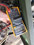
10 terminal block reads 12.2 on upper wires, not disconnected. Little tricky to get in there. A1 test, with wires disconnected is a crazy bizarre reading in the 60.0 range. I triple checked it and every time got a different reading, but it was definitely no lower than 50-60 ohms
 

kloppk

Well-known member
Steel Soldiers Supporter
2,284
4,028
113
Location
Pepperell, Massachusetts
The resistance should be the same 12.2 at 10 Terminal block AND across the two wires behind the gauge panel.
Your 50-60 ohms indicates a poor connection between 10 and one or both of those wires.
I mentioned to check, inspect, clean the P4/J4 connector pins in post #12. Did you do that?
 

Iron.Horse

New member
13
15
3
Location
Frederick, Maryland
The resistance should be the same 12.2 at 10 Terminal block AND across the two wires behind the gauge panel.
Your 50-60 ohms indicates a poor connection between 10 and one or both of those wires.
I mentioned to check, inspect, clean the P4/J4 connector pins in post #12. Did you do that?
Yes sir, found J5, pulled it apart and sprayed it with electronics cleaner. I honestly have looked everywhere for P5 but haven't found it yet. I'll try to look again for it.
 

kloppk

Well-known member
Steel Soldiers Supporter
2,284
4,028
113
Location
Pepperell, Massachusetts
Your DMM is actually displaying 76,300 ohms (7.6 KOhms)

P5 and J5 connect together.
J5 is bolted to the floor of the compartment behind the gauges. A small black connector with 4 wires..
P5 plugs into J5 behind the right access door.
P5 also has 4 wires.

Do you know how to decipher the -24 TM to figure exactly how it's wired from A1 to find 10?
The TM wiring method can be confusing to figure out...

edit:

Here is a quick drawing showing the actual wiring...
1750459137858.png
 
Last edited:

Iron.Horse

New member
13
15
3
Location
Frederick, Maryland
Your DMM is actually displaying 76,300 ohms (7.6 KOhms)

P5 and J5 connect together.
J5 is bolted to the floor of the compartment behind the gauges. A small black connector with 4 wires..
P5 plugs into J5 behind the right access door.
P5 also has 4 wires.

Do you know how to decipher the -24 TM to figure exactly how it's wired from A1 to find 10?
The TM wiring method can be confusing to figure out...

edit:

Here is a quick drawing showing the actual wiring...
View attachment 949149
I Really, Really appreciate the drawing and help... The tracing of wires makes a lot of sense, I pulled J5 again and sprayed it, traced the wires and looked for rubs and chews, they look fine. The original spade connectors were replaced with permanent crimps, wires seem solid. I guess I could cut them out and re-splice for good measure? Wires seem fine going into gen head, no rubs, but I can't see where the one set terminates on the... coil? Only the other set on number 10.

Should I cut out the larger wire that lays on the gen head and replace from the plug to where it enters the head? That would eliminate a few feet of wire that could have internal damage?
 
Top