410Customs
Member
- 46
- 30
- 18
- Location
- North Idaho
Thanks fellas
Unfortunately for me it is one step forward and two steps back with this thing.
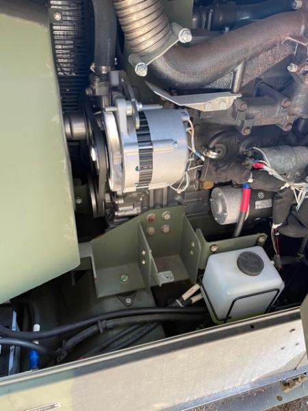
The new alternator is in! AND
Drum roll please..........................
NOT WORKING!
So yeah seriously now we have a new issue.
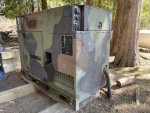
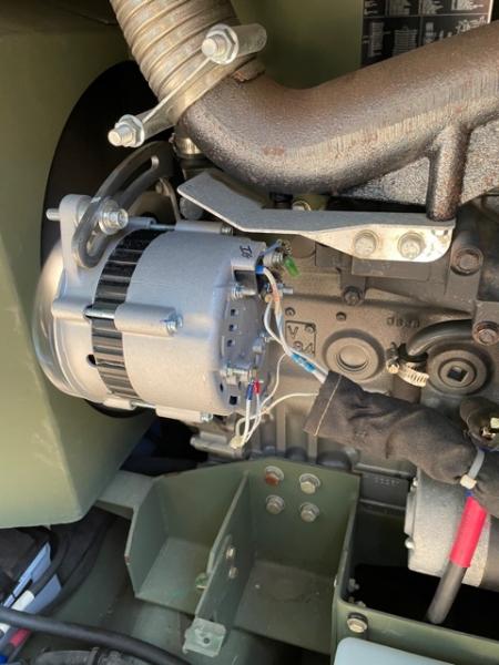
The new alternator installed is a 24V, 40 AMP unit
Installed just fine, wired up same as the old one, bolted right up, belt is tight
NATCAD I love this topic!! We are in the market for some new panels and a 3rd inverter...etc but that will have to wait until I can sort this charging issue out
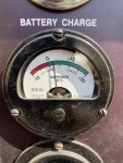
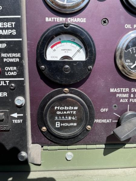
As soon as I start the generator the ammeter pegs past +20 and in a few seconds the 25 amp circuit breaker pops and the unit quits charging
So I tried moving the ground wire, same thing
I get my multimeter out and check battery voltage
Before the circuit breaker blows the battery voltage was climbing....23.5, 24, 25....when it gets to 25.5 the circuit breaker pops and the alternator quits charging.
WHAT THE HECK IS GOING ON WITH THIS THING????????
The system should charge at 25-27 volts.
This is a new alternator tested before I installed it
So now I'm guessing we can see why the old Hitachi unit was failed, something is fishy
Lucky for me the battery charger I ordered on Amazon came and I was using that yesterday to recharge the batteries.
This is a Norco 2600 24V battery charger, I plug it in to the courtesy outlets and set it on 24V, hooked up to the battery bank...it was charging them just fine
So now I am thinking, well maybe I cannot use glass matt batteries in this unit? So I did some research
Nope........ the Optima red tops it came with were glass matt and they were approved for use in this unit
Are the batteries I installed too large? Drawing too many amps? I do not see how that is possible, they are just Everstart 12V group 65 AGM batteries
The gauge pegs way past +20 amps.........
IO have checked the battery wiring and alternator wiring 100 times, I know it is hooked up correctly
So do I have a bad circuit breaker (not likely)
what causes an ammeter to PEG? (too many amps right?)
Why would it be pulling too many amps enough to blow the CB every time?
New unit
Now I am starting to see why I got such a good deal on this thing
Any ideas on where to start?
New shunt? New circuit breaker? I am not a big fan on throwing parts at a machine, I would rather know what the heck to test!!
NOT GOOD!!!!!!
Our ducks:

our elk herd

Unfortunately for me it is one step forward and two steps back with this thing.
The new alternator is in! AND
Drum roll please..........................
NOT WORKING!
So yeah seriously now we have a new issue.
The new alternator installed is a 24V, 40 AMP unit
Installed just fine, wired up same as the old one, bolted right up, belt is tight
NATCAD I love this topic!! We are in the market for some new panels and a 3rd inverter...etc but that will have to wait until I can sort this charging issue out
As soon as I start the generator the ammeter pegs past +20 and in a few seconds the 25 amp circuit breaker pops and the unit quits charging
So I tried moving the ground wire, same thing
I get my multimeter out and check battery voltage
Before the circuit breaker blows the battery voltage was climbing....23.5, 24, 25....when it gets to 25.5 the circuit breaker pops and the alternator quits charging.
WHAT THE HECK IS GOING ON WITH THIS THING????????
The system should charge at 25-27 volts.
This is a new alternator tested before I installed it
So now I'm guessing we can see why the old Hitachi unit was failed, something is fishy
Lucky for me the battery charger I ordered on Amazon came and I was using that yesterday to recharge the batteries.
This is a Norco 2600 24V battery charger, I plug it in to the courtesy outlets and set it on 24V, hooked up to the battery bank...it was charging them just fine
So now I am thinking, well maybe I cannot use glass matt batteries in this unit? So I did some research
Nope........ the Optima red tops it came with were glass matt and they were approved for use in this unit
Are the batteries I installed too large? Drawing too many amps? I do not see how that is possible, they are just Everstart 12V group 65 AGM batteries
The gauge pegs way past +20 amps.........
IO have checked the battery wiring and alternator wiring 100 times, I know it is hooked up correctly
So do I have a bad circuit breaker (not likely)
what causes an ammeter to PEG? (too many amps right?)
Why would it be pulling too many amps enough to blow the CB every time?
New unit
Now I am starting to see why I got such a good deal on this thing
Any ideas on where to start?
New shunt? New circuit breaker? I am not a big fan on throwing parts at a machine, I would rather know what the heck to test!!
NOT GOOD!!!!!!
Our ducks:
our elk herd
Last edited:
")