• Steel Soldiers now has a few new forums, read more about it at: New Munitions Forums!

  • Microsoft MSN, Live, Hotmail, Outlook email users may not be receiving emails. We are working to resolve this issue. Please add support@steelsoldiers.com to your trusted contacts.

MEP 805B display problem found.

155mm

Chief and Indian
Steel Soldiers Supporter
1,181
397
83
Location
Guymon, OK
What is y'all's opinion on putting a couple desiccate packets in the case?
 

Guyfang

Moderator
Staff member
Moderator
16,924
24,545
113
Location
Burgkunstadt, Germany
Cant hurt. We often took things like this home, and put them in the oven first. Use only a tiny bit of heat, for several hours. Then put it back together using RTV and some desiccants.
 

baxter462

Member
79
2
8
Location
Salt Lake City Utah
Okay,

I have finally fixed my CIM's screen issue that I first mentioned in this tread:

http://www.steelsoldiers.com/showthread.php?162166-Mep-805b-display-issues

I replaced the LCD panel, and it didn't make a difference, ghosting issue was still present. I decided to check the resistance of each conductor in the ribbon cable from the CIM's computer motherboard to the the LCD panel, and I found several circuits with very high resistance. I pinpointed the excessive resistance to the area where the large ribbon cable connectors "crimp" on to the ribbon cable (the terminals of the connector pierce through the insulation and make contact with the conductors in the cable). I removed the connectors, cut off about 3/8" of ribbon cable, cleaned the barbs of the connectors' terminals with DeoxIT, and carefully crimped them back on. Retested the resistance afterwards. Looked good, so I reassembled the CIM and tested it. Works perfectly!

20170103_201129.jpg

20170103_182809.jpg

20170103_182755.jpg
 

155mm

Chief and Indian
Steel Soldiers Supporter
1,181
397
83
Location
Guymon, OK
Ok, finally took the time to look at this thread and figure out how to build this without getting the wrong wires.....
https://www.steelsoldiers.com/showt...Interface-Module)-Brighten-Darken-Information

so we pushed the ez button rather than try to find 6 wires in a 100 wire bundle.

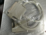
100 pin scsi cable- on order from Isreal
Screenshot_12.png

100 pin scsi cable wire break out block- poh today.
IMG_1743[1].jpg

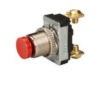
next on the list will be 2 push button switches, 1 for lighting and 1 for dimming
Screenshot_13.png

and an regular on/off switch for the display.
Screenshot_14.png

We will get it built now that winter is getting closer and shop time in front of a heater is much better than outside in the cold.
 

155mm

Chief and Indian
Steel Soldiers Supporter
1,181
397
83
Location
Guymon, OK
Delay of game, shipper sent me a 50 pin cable, not 100... well this project gets set back on the shelf.

I guess if you count both ends, he did send me a 100 pin cable.
 

155mm

Chief and Indian
Steel Soldiers Supporter
1,181
397
83
Location
Guymon, OK
Okay,

I have finally fixed my CIM's screen issue that I first mentioned in this tread:

http://www.steelsoldiers.com/showthread.php?162166-Mep-805b-display-issues

I replaced the LCD panel, and it didn't make a difference, ghosting issue was still present. I decided to check the resistance of each conductor in the ribbon cable from the CIM's computer motherboard to the the LCD panel, and I found several circuits with very high resistance. I pinpointed the excessive resistance to the area where the large ribbon cable connectors "crimp" on to the ribbon cable (the terminals of the connector pierce through the insulation and make contact with the conductors in the cable). I removed the connectors, cut off about 3/8" of ribbon cable, cleaned the barbs of the connectors' terminals with DeoxIT, and carefully crimped them back on. Retested the resistance afterwards. Looked good, so I reassembled the CIM and tested it. Works perfectly!

View attachment 661211

View attachment 661212

View attachment 661213
Which cable did you trim? the 100 wire ribbon that the connector from the outside? the other screen control cable is the 8 wire connector that connects on the same board as where the power connects to.
 

baxter462

Member
79
2
8
Location
Salt Lake City Utah
I trimmed the ribbon cable that runs from the motherboard to the LCD panel inside the CIM. There are several CIM designs though (I've personally seen 3 different styles, but there are probably more). Only one of the three types I've dealt with uses the cable I'm referring to, the others use different kinds of cables. The one in question has a color screen, no external USB port, 4.1.1a software, and a winsystems SAT-520Plus motherboard.

By the way, the contrast adjustment tool you're building doesn't work on CIMs with color screens, it only works for the old monochrome screens.
 

Guyfang

Moderator
Staff member
Moderator
16,924
24,545
113
Location
Burgkunstadt, Germany
I don't remember ever seeing a color CIM having a contrast problem. But when I stopped contracting, the color CIM was still rare to see. They were just really starting to be issued. And almost all were going into new gen sets. As always, production lagged behind demand. Another impact on the lack of color CIM's was the fact that units knew that it was a problem area for the set. So they ordered "extra" CIM's, and rat holed them. At one point, CIM's and Backplanes were simply impossible to get. A unit that had just came back from down range was unloading multipack boxes of their "extra, nice to have" crap, and I found 6 CIM's and about 8 or 9 Backplanes! The CWO was a friend of mine and gave me half of all his loot. I used them all within a week. Made lots of folks happy. And the parts were returnable. Normally, you have to have a unserviceable to get a serviceable! CECOM tried to get this under control, but never did manage to compleatly do so. At one point, every requesting unit had to be checked by a CECOM representive to insure that they had a valid need for the part, and not just wanted an extra.

Just a little history on the CIM.
 

peapvp

Well-known member
Steel Soldiers Supporter
1,122
1,255
113
Location
Basehor, KS
Your BIOS Date shows 1-31-93, indicating that the Battery is out. This is the Winsystem Board Version you got. Battery has to be changed first to keep any BIOS settings other then BIOS default. Your IDE defaults to 3 - it could be another setting for your DOC / HDD - you need to hook up a standard 101 Keyboard and then enter the BIOS after the Battery has been replaced.
This mother board also has the standard IDE Connectors on the PCB to hook up a regular Hard Drive and a Floppy / CD ROM . The system is normally booted the first Time Windows CE or better the DOS part of Windows CE which contains CD-ROM Drivers when first assembled. After the Hard Drive has been formatted, you can install then DOS Part with Drivers which will give you access to the CD-ROM. From there you can reinstall Windows CE ( I think Rev 4) and then the actual CIM Software which is available on CD. Any Microsoft DOS 6.xx Version will work to get a HDD / DOC formatted and ready for installation.

DOC's, because of their nature, have only a limited erase and write cycles before they fail. They cannot be deep level formatted or fixed by using chdsk or fdisk commands from DOS or the very old BIOS HDD Sector repair utility. The silicone is toast. To erase a byte or a block of bytes, the normal voltage on the DOC has to be increased. Depending on the DOC from normally 5 Volt to somewhere between 10 to 15Volt. The board does this automatically when ever a erase / write cycle is executed. It has an internal charge pump with an external capacitor as oscillator to accomplish this task.

The amount of cycles for those Solid State Devices is usually around 250,000 to 500,000 Write/Erase Cycles for the live of the chip. After that you can expect a performance degradation resulting in total device failure after some time.

The read cycles are unlimited, since those happen at the 5 Volt Level.

You can also replace DOC with exactly the same one and follow the same procedure as with the Hard Drive (formatting etc.)

This will catapult you back in to the mid nineties computing area as this is a 486 CPU (486DX2) running at 16 or 25 MHz
 

peapvp

Well-known member
Steel Soldiers Supporter
1,122
1,255
113
Location
Basehor, KS
We have the following additional parts available to fix / repair those Winsystem setup's:

Battery G111-0047-000 ( needs to be de-soldered / soldered )

Mouse Cable CBL-343-G-1-1.375 ( to connect regular PS/2 Mouse )

Keyboard Cable CBL-247-G-1-1.0 ( to connect standard 101/102 Keyboard )

Video Cable CBL-234-G-1-1.375 ( to connect a regular VGA / SVGA Monitor instead of LCD )

Please PM me for pricing and availability
 

TheAlfredo

Member
165
11
18
Location
Miami, FL
@TheAlfredo, are you asking if the display is repaired or if the bright/dark tool got built?

answers are yes and yes
I have screen that looks like it spent too much time in the sun. It has for lack of a better word...a bubble right in the middle. Not sure if its the screen....or just the plastic in front of it. Haven't had a chance to take it apart yet. But I would like to get it fixed if it is the screen
 

155mm

Chief and Indian
Steel Soldiers Supporter
1,181
397
83
Location
Guymon, OK
The video shows with contrast full light. Does that what you mean by in the sun too long?

now the bubble is a physical fault so only way to fix that is maybe pull one of the layers or replace the screen
 
Top
AdBlock Detected

We get it, advertisements are annoying!

Sure, ad-blocking software does a great job at blocking ads, but it also blocks useful features of our website like our supporting vendors. Their ads help keep Steel Soldiers going. Please consider disabling your ad blockers for the site. Thanks!

I've Disabled AdBlock
No Thanks