• Steel Soldiers now has a few new forums, read more about it at: New Munitions Forums!

  • Microsoft MSN, Live, Hotmail, Outlook email users may not be receiving emails. We are working to resolve this issue. Please add support@steelsoldiers.com to your trusted contacts.

MEP-831a Inverter Overhaul

marcjs14

Member
35
34
18
Location
NC
Peter,

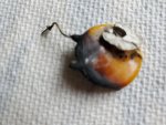
Here are the two sides of the ceramic capacitor? in question. Only one leg needed de-soldering as the other vaporized (thus the sad appearance)...
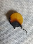
20220820_135757.jpg

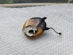
I haven't removed the silicon which held it to the electrolytic cap, but instead photographed her sister (after peeling her away from equivalent electrolytic partner). Same markings as posted by kloppk
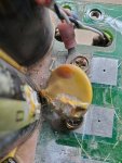
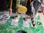
20220820_134702.jpg20220820_134718.jpg
 

Attachments

marcjs14

Member
35
34
18
Location
NC
Not sure why one of them posted as an attachment...oh well.

In regards to continuity, open-circuit between the stub of disintegrated leg and the intact one.
 

peapvp

Well-known member
Steel Soldiers Supporter
1,103
1,210
113
Location
Basehor, KS
Peter,

Here are the two sides of the ceramic capacitor? in question. Only one leg needed de-soldering as the other vaporized (thus the sad appearance)...
View attachment 876640

I haven't removed the silicon which held it to the electrolytic cap, but instead photographed her sister (after peeling her away from equivalent electrolytic partner). Same markings as posted by kloppk

View attachment 876643View attachment 876642
thank you Marcel. Quite a violent distraction.
I was not able to clarify by the Markings if this is a varistor or ceramic capacitor yet
However, the damage to the part is more inline with the way Varistors fail then Ceramic Capacitors.
Ceramic Capacitors usually just blow a small hole on one side and release white smoke with has a very distinct smell to it
 

peapvp

Well-known member
Steel Soldiers Supporter
1,103
1,210
113
Location
Basehor, KS
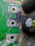
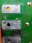
The front and back-side of the board where it was soldered...
View attachment 876645View attachment 876646
this damage is more consistent with metal oxide. It burns hotter then ceramics.

Anyway, let’s say it’s a ceramic cap then it would be a 0.01uF 1000V 20% cap
I cannot clearly locate the manufacturer of this cap - usually the letters gives you an idea unless that info was on the other side of cap
 

peapvp

Well-known member
Steel Soldiers Supporter
1,103
1,210
113
Location
Basehor, KS
Ok, the next thing then would be to remove the electrolytic’s since you had mentioned before that you had received replacements if I remember that correctly
I would check the diodes etc on the other board now too
 

peapvp

Well-known member
Steel Soldiers Supporter
1,103
1,210
113
Location
Basehor, KS
The PCB even though burnt seems to be ok. When you remove the electrolytic’s then you will be able to see the traces and continuity check them
 

kloppk

Well-known member
Steel Soldiers Supporter
2,126
3,492
113
Location
Pepperell, Massachusetts
Kurt, the one you got is Cermaic Cap, no question. Is there anywhere in your circuit a inrush limiter that your aware off?
It is hard to believe that they have no inrush current limiting with those 12 large caps. The inrush current is pretty high when they are empty and the system first fires up
I'll tear my inverter down more and see if there is an inrush limiter.
 

peapvp

Well-known member
Steel Soldiers Supporter
1,103
1,210
113
Location
Basehor, KS
Peter,
should I be checking the alternator first before going any further with the inverter? Could the problem have originated there? Certainly just prior to the smoke pouring out I heard something which could best be described as some sort of mechanical rubbing sound.

Thx,
Marcel
Marcel,

i didn’t mean to ignore this vital question here, but I wanted to see first the cap/varistor.
Because if it is only this part which went bad besides aging electrolytic’s then there is nothing to worry about.
In either case, the burnt cap/varistor serve more or less the same function where as the varistor is basically a ceramic cap on steroids.

If your diodes and transistor modules check out good and we have no shorted electrolytic’s then the cap / varistor failure can be attributed to a standalone component failure with no other affected components and the repair would be pretty much straight forward. Just very time consuming and tedious to replace a few caps.

Peter
 

peapvp

Well-known member
Steel Soldiers Supporter
1,103
1,210
113
Location
Basehor, KS
Marcel,

i just looked through the other pictures of the other circuit board and saw that one board had several of these cap/Varistors on it. Can you locate one off those which preferably has the same number / letters as the burnt one and post a pic of the other side of a good one.
This way I can hopefully locate the manufacturer of the Cap

The M indicates that is cap with 20% tolerance - the H has no meaning other then a identification for a Taiwanese / Chinese Cap Manufacturer Hitano, but there Caps / Varistors are blue
 

kloppk

Well-known member
Steel Soldiers Supporter
2,126
3,492
113
Location
Pepperell, Massachusetts
Peter,

No inrush limiter. DC goes from diode bridge directly to the electrolytics.
Only other parts on the assembly besides the two disc caps are a couple of caps between the power transistors and two bleeder resisters.

I suspect it doesn't need a limiter since the PMA voltage rises as the generator spins up.
 

peapvp

Well-known member
Steel Soldiers Supporter
1,103
1,210
113
Location
Basehor, KS
Peter,

No inrush limiter. DC goes from diode bridge directly to the electrolytics.
Only other parts on the assembly besides the two disc caps are a couple of caps between the power transistors and two bleeder resisters.

I suspect it doesn't need a limiter since the PMA voltage rises as the generator spins up.
yes, but current precedes the voltage with e caps which means the diodes and power transistor are working into a “short” when the system starts up.
Piss poor design for an inverter application…..
 

kloppk

Well-known member
Steel Soldiers Supporter
2,126
3,492
113
Location
Pepperell, Massachusetts
i just looked through the other pictures of the other circuit board and saw that one board had several of these cap/Varistors on it. Can you locate one off those which preferably has the same number / letters as the burnt one and post a pic of the other side of a good one.

Peter,

Here are front and back pics of the same part on the top board.
Ref Des on the PCB for it is C19
Cap Front.jpg

No marking on the back
Cap Back.jpg
 

peapvp

Well-known member
Steel Soldiers Supporter
1,103
1,210
113
Location
Basehor, KS
Marcel,

since Kurt just mentioned this, there seem to be two more of these disc caps and two other caps on this board.

i would replace these disc caps with Murata or Vishay Caps

once we hopefully find out who made those caps then I can cross reference them to Murata or Vishay Caps
 

peapvp

Well-known member
Steel Soldiers Supporter
1,103
1,210
113
Location
Basehor, KS
The M in the square is the Tolerance = 20%
The H indicates Hitano Caps. Taiwanese passive component manufacturer with actual manufacturing facilities in China,
Basically Chinese crap custom made in yellow instead of their regular blue
 

peapvp

Well-known member
Steel Soldiers Supporter
1,103
1,210
113
Location
Basehor, KS
These US Corporate Leaders and their Beancounters are not in the here and now anymore…….
 

marcjs14

Member
35
34
18
Location
NC
Peter and Kurt, I am so grateful for your assistance with this project!

I am a mechanical engineer by education, but unafraid of electrical work - which often leads me beyond my knowledge/understanding. Nonetheless, I am happy to learn.

I tested the diodes in-circuit on both sides of the inverter (the burnt and unburnt sides). Using my antiquated Fluke 16 in diode mode, all diodes pass in forward-bias direction with a voltage drop of ~0.4-0.45V. In reverse-bias, the unburnt side voltage drop climbs to ~2.3V before showing the good OL, whereas the burnt plateaus around 1V, and never gives the OL check. Is that an indication that all those diodes are fried, or could the removal of that ceramic disc capacitor be impacting the reverse-bias measurements in some way (as you see I am now clearly out of my lane ;) )
 
Top