Looks like I might be reviving an older thread. But I recently picked up one of these Miltope computers from a yardsale and on my quest to revive the hunk of aluminum I found this forum.
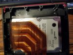
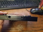
Of course it was my luck that the unit did not have the HDD caddy and the guy I bought it from didn't know anything about it. I've stripped the thing down and found out the proprietary connector inside is 50 pins. The mother-board and ribbon cable to the connector both mark pins 1-50. However, I am unsure how this translates to the pinout of an IDE ATA drive (whether pin 1 is the "first" pin on the drive, etc).
That said, any of you folks on here know how this pinout interfaces to the HDD? Perhaps one of you who may have a caddy and/or cable that works as intended would be willing to perform a continuity test with a multimeter, between the connector that plugs into the computer and the connector that plugs into the HDD? I would be very grateful.
My plan is to ultimately create my own from scratch (and also include an adapter to get a modern SSD into it), which is no issue for me. I just need to fully understand the pinout first. If successful, I'd be willing to share a detailed walkthrough of what I do should any body else in the same tough-spot need it.
Thanks and fingers crossed!