• Steel Soldiers now has a few new forums, read more about it at: New Munitions Forums!

  • Microsoft MSN, Live, Hotmail, Outlook email users may not be receiving emails. We are working to resolve this issue. Please add support@steelsoldiers.com to your trusted contacts.

Miltope MSD V2

CAFRS

New member
3
5
3
Location
United States
Looks like I might be reviving an older thread. But I recently picked up one of these Miltope computers from a yardsale and on my quest to revive the hunk of aluminum I found this forum.

Of course it was my luck that the unit did not have the HDD caddy and the guy I bought it from didn't know anything about it. I've stripped the thing down and found out the proprietary connector inside is 50 pins. The mother-board and ribbon cable to the connector both mark pins 1-50. However, I am unsure how this translates to the pinout of an IDE ATA drive (whether pin 1 is the "first" pin on the drive, etc).

That said, any of you folks on here know how this pinout interfaces to the HDD? Perhaps one of you who may have a caddy and/or cable that works as intended would be willing to perform a continuity test with a multimeter, between the connector that plugs into the computer and the connector that plugs into the HDD? I would be very grateful.

My plan is to ultimately create my own from scratch (and also include an adapter to get a modern SSD into it), which is no issue for me. I just need to fully understand the pinout first. If successful, I'd be willing to share a detailed walkthrough of what I do should any body else in the same tough-spot need it.

Thanks and fingers crossed!
 

Mullaney

Well-known member
Steel Soldiers Supporter
Supporting Vendor
7,829
20,021
113
Location
Charlotte NC
Looks like I might be reviving an older thread. But I recently picked up one of these Miltope computers from a yardsale and on my quest to revive the hunk of aluminum I found this forum.

Of course it was my luck that the unit did not have the HDD caddy and the guy I bought it from didn't know anything about it. I've stripped the thing down and found out the proprietary connector inside is 50 pins. The mother-board and ribbon cable to the connector both mark pins 1-50. However, I am unsure how this translates to the pinout of an IDE ATA drive (whether pin 1 is the "first" pin on the drive, etc).

That said, any of you folks on here know how this pinout interfaces to the HDD? Perhaps one of you who may have a caddy and/or cable that works as intended would be willing to perform a continuity test with a multimeter, between the connector that plugs into the computer and the connector that plugs into the HDD? I would be very grateful.

My plan is to ultimately create my own from scratch (and also include an adapter to get a modern SSD into it), which is no issue for me. I just need to fully understand the pinout first. If successful, I'd be willing to share a detailed walkthrough of what I do should any body else in the same tough-spot need it.

Thanks and fingers crossed!
.
Don't know for sure because I have never seen one. Could be a 50pin SCSI (before fast wide 68 pin SCSI) or depending on who built it, IBM had 50 pin IDE drives with power built into those connectors.
 

CAFRS

New member
3
5
3
Location
United States
.
Don't know for sure because I have never seen one. Could be a 50pin SCSI (before fast wide 68 pin SCSI) or depending on who built it, IBM had 50 pin IDE drives with power built into those connectors.
That does look promising, at least from some images I've seen it has the parallel pins in a male connection (the connection to the Miltope looks to be female). I don't have one handy to compare the size.

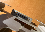
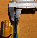
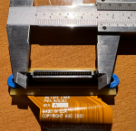
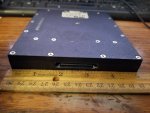
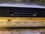
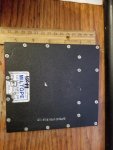
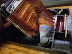
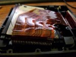
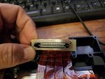
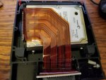
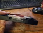
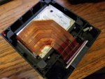
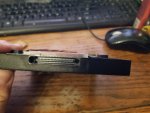
I'll toss in some pictures of the connector in the Miltope, maybe it'll help give a better idea of it?

connect1.PNG
connect2.PNG
connect3.PNG

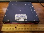
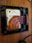
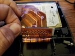
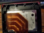
This is what the ribbon cable to the mother-board looks like, just to show what I mentioned earlier.

connect4.PNG
 

Mullaney

Well-known member
Steel Soldiers Supporter
Supporting Vendor
7,829
20,021
113
Location
Charlotte NC
That does look promising, at least from some images I've seen it has the parallel pins in a male connection (the connection to the Miltope looks to be female). I don't have one handy to compare the size.

I'll toss in some pictures of the connector in the Miltope, maybe it'll help give a better idea of it?

View attachment 870463
View attachment 870464
View attachment 870465

This is what the ribbon cable to the mother-board looks like, just to show what I mentioned earlier.

View attachment 870466
.
Dang. Yessir, seems "similar but different" and a PS2 Connector and the connections are definitely backward to use those parts.

Sorry. I was hopeful.

My guess is that part of the MILTOPE folks made it the way they did intentionally. All parts would have to come from them is my guess.
 

CAFRS

New member
3
5
3
Location
United States
.
Dang. Yessir, seems "similar but different" and a PS2 Connector and the connections are definitely backward to use those parts.

Sorry. I was hopeful.

My guess is that part of the MILTOPE folks made it the way they did intentionally. All parts would have to come from them is my guess.
Yeah manufacturers like to do that, with all their proprietary connectors that you have to get from them. I'm still hopeful that someone might be able to do a continuity test on an existing HDD caddy or cable to provide the exact pinout. From there I'd be able to replicate my own connector/adapter from scratch.
 

LwCwb08

Member
14
48
13
Location
Berlin, NJ
Well since this thread has been revived... I'm looking for a copy of the EMS-2 viewer. Mine is somehow corrupted (looking for a .dpl config file). Anybody got a way of getting me that please shoot me a PM.
 

Wile E. Coyote

Active member
394
78
28
Location
Lynden WA
Now that Uncle has decided to release a bunch of these I have an NOS one but less the HDD caddy same as everyone else.

Did anyone ever create a pinout? I was hoping the thing would be SATA but no such luck. I see someone back aways said they managed to USB boot it with Puppy Linux but on mine there's no facility to add USB as a boot option in BIOS . I haven't tried to see if it'll do it anyway.

What are people doing for power? If you were lucky enough to get one of the kits vs. just the basic machine you'll have the AC adaptor, but I've never seen any of those in the wild by themselves. Vendors usually have the slave cable power cord for them but the OG power supply would be better. I can always make my own if I know the Amphenol connector part numbers.

In the lot of them I pulled my one out of, I noticed a bunch of the screens were delaminating. Didn't look into it too deeply so it might just be an applique screen protector that's bubbling away (in fact it probably is) - but obviously some storage conditions factor isn't being too kind to whatever process used to glue that lot together.
 
Top
AdBlock Detected

We get it, advertisements are annoying!

Sure, ad-blocking software does a great job at blocking ads, but it also blocks useful features of our website like our supporting vendors. Their ads help keep Steel Soldiers going. Please consider disabling your ad blockers for the site. Thanks!

I've Disabled AdBlock
No Thanks